
MATH-101 · Lesson 11 of 12 · 33 min
Integrals in engineering: beams, fluids and heat
Engineering analysis repeatedly follows the same pattern: a physical law describes what happens in a tiny element of a structure, a fluid or a solid, and integration adds up the elements to give the behavior of the whole. Lesson 3 used this pattern for volumes and work, and Lesson 4 for centroids and moments. This lesson applies it to three areas that every engineering student meets in the second year: the bending of beams, the flow of fluids in pipes and the atmosphere, and the conduction of heat through walls and insulation. In each case, setting up the integral from a small element is the essential skill, and the integration techniques of this course do the rest. The results are classic formulas found in every engineering handbook; deriving them shows where they come from and when they apply.
Loads, shear and bending moment
A beam carries loads across a span. At any section, the material to one side exerts on the other a shear force \(V\) (perpendicular to the beam) and a bending moment \(M\). Considering the equilibrium of a short slice of length \(dx\) carrying a distributed load \(w(x)\) (force per unit length, positive downward) gives two simple relations:
So the shear force is an integral of the load, and the bending moment an integral of the shear force. The constants of integration come from the support conditions: at a simple support or free end, the bending moment is zero; at a free end, the shear force is also zero. The bending moment is largest where the shear force is zero, a direct application of Calculus I.
Worked problem
A uniformly loaded beam
A simply supported beam of span \(L\) carries a uniform load \(w\). Find the shear force and bending moment along the beam, and the maximum moment.
Show solution
- By symmetry each support carries \(wL/2\), so \(V(0) = wL/2\).
- Integrate \(dV/dx = -w\): \(V(x) = \dfrac{wL}{2} - wx\).
- Integrate \(dM/dx = V\) with \(M(0) = 0\): \(M(x) = \dfrac{wL}{2}x - \dfrac{w}{2}x^2 = \dfrac{w}{2}x(L - x)\).
- Maximum where \(V = 0\), at \(x = L/2\): \(M_{max} = \dfrac{wL^2}{8}\).
Answer: A parabolic bending moment diagram peaking at wL²/8 at midspan, the most used formula in structural design. For a 6 m floor beam carrying 10 kN/m, the maximum moment is 45 kN·m.
Deflection of beams
Bending curves a beam. For small deflections \(y(x)\), the curvature is approximately \(y''\), and the Euler-Bernoulli beam theory relates it to the bending moment:
where \(E\) is the modulus of elasticity of the material and \(I\) the second moment of area of the cross-section (Lesson 4). Integrating twice gives the deflected shape, with two more constants fixed by the supports: zero deflection at supports, and zero slope at a built-in (fixed) end or at a point of symmetry. Combining with the load relations gives a single fourth-order equation, \(EI\,y'''' = -w(x)\) (with \(y\) measured upward), which can be integrated four times.
Worked problem
Midspan deflection of a uniformly loaded beam
Find the deflection curve and the maximum deflection of the simply supported beam above, with \(y\) measured upward (a sagging beam has negative \(y\) and, under a sagging moment, positive curvature).
Show solution
- \(EI\,y'' = M = \dfrac{w}{2}(Lx - x^2)\).
- Integrate: \(EI\,y' = \dfrac{w}{2}\left(\dfrac{Lx^2}{2} - \dfrac{x^3}{3}\right) + C_1\). By symmetry \(y'(L/2) = 0\), giving \(C_1 = -\dfrac{wL^3}{24}\).
- Integrate again: \(EI\,y = \dfrac{w}{2}\left(\dfrac{Lx^3}{6} - \dfrac{x^4}{12}\right) - \dfrac{wL^3}{24}x + C_2\), and \(y(0) = 0\) gives \(C_2 = 0\).
- Simplify: \(y(x) = -\dfrac{w}{24EI}\left(x^4 - 2Lx^3 + L^3x\right)\). At \(x = L/2\): \(y = -\dfrac{5wL^4}{384EI}\).
Answer: The maximum deflection is 5wL⁴/(384EI). For a steel beam (E = 200 GPa) with I = 8.0 × 10⁻⁵ m⁴, spanning 6 m under 10 kN/m: 5 × 10,000 × 6⁴/(384 × 2 × 10¹¹ × 8 × 10⁻⁵) = 10.5 mm, or span/570, within the span/360 limit commonly applied to floors.
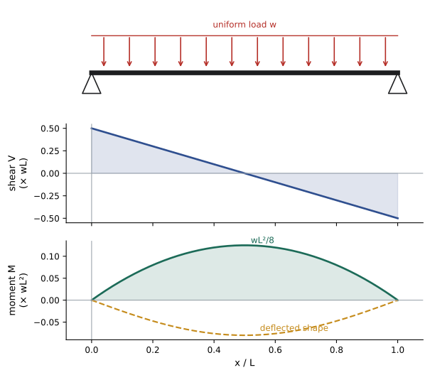
The deflection grows with the fourth power of the span, so doubling the span of a beam multiplies its deflection by 16 under the same load per meter. This strong dependence, visible only through the integration, explains why long-span structures require much deeper sections.
Flow rate from a velocity profile
Fluid flowing through a pipe does not move at the same speed everywhere: friction holds it still at the wall, and it moves fastest at the center. The volume flow rate through the pipe is found by dividing the cross-section into thin rings. A ring of radius \(r\) and width \(dr\) has area \(2\pi r\,dr\), and fluid passes through it at speed \(u(r)\), so:
For slow, steady (laminar) flow of a viscous fluid, the velocity profile is a parabola, \(u(r) = u_{max}\left(1 - \dfrac{r^2}{R^2}\right)\), a result known as Hagen-Poiseuille flow.
Worked problem
Laminar flow in a tube
Find the flow rate and average velocity for the parabolic profile, and the flow of oil in a 20 mm diameter tube with a centerline velocity of 0.5 m/s.
Show solution
- \(Q = 2\pi u_{max}\displaystyle\int_0^R \left(r - \frac{r^3}{R^2}\right)dr = 2\pi u_{max}\left(\frac{R^2}{2} - \frac{R^2}{4}\right) = \frac{\pi R^2 u_{max}}{2}\).
- Average velocity: \(\bar{u} = Q/(\pi R^2) = u_{max}/2\).
- For \(R = 0.01\) m and \(u_{max} = 0.5\) m/s: \(Q = \pi \times 10^{-4} \times 0.25 = 7.85 \times 10^{-5}\) m³/s, about 4.7 L/min.
Answer: In laminar flow the average velocity is exactly half the centerline value. In turbulent flow the profile is much flatter and the average is about 80 percent of the maximum, which is why flow meters that sample velocity at one point must be calibrated for the flow regime.
The same ring integral gives the momentum and kinetic energy carried by the flow. Because kinetic energy depends on \(u^3\), the energy flux of a non-uniform profile exceeds that computed from the average velocity: for laminar flow by a factor of 2, which fluid mechanics courses include as a kinetic energy correction factor.
Pressure in a fluid at rest and in the atmosphere
In a fluid at rest, the pressure increases with depth because each layer supports the weight of the fluid above. For a thin layer of thickness \(dz\), the balance of forces gives:
with \(z\) measured upward. For a liquid of constant density, integrating gives the familiar \(P = P_0 + \rho g h\) at depth \(h\). In the atmosphere the density is not constant: by the ideal gas law, \(\rho = PM/(RT)\), where \(M\) is the molar mass of air and \(R\) the gas constant. If the temperature is taken as constant, the equation becomes separable (Lesson 5):
Worked problem
Pressure at altitude
With \(T = 288\) K, \(M = 0.029\) kg/mol, \(R = 8.314\) J/(mol·K) and \(g = 9.81\) m/s², find the scale height \(H\) and the pressure at 2,500 m, where many mines and some data centers operate, if sea-level pressure is 101.3 kPa.
Show solution
- \(H = \dfrac{8.314 \times 288}{0.029 \times 9.81} = 8{,}420\) m.
- \(P = 101.3\,e^{-2500/8420} = 101.3 \times 0.743 = 75.3\) kPa.
Answer: About 75 kPa, roughly three-quarters of sea-level pressure. The air density is similarly reduced, which lowers cooling capacity and engine power, which is why equipment is derated at altitude (ELE-470). The real atmosphere cools with height, which changes the numbers slightly but not the method.
Heat conduction through walls and insulation
Fourier's law of heat conduction states that the heat flow rate \(q\) through a material is proportional to the area \(A\) and the temperature gradient: \(q = -kA\,\dfrac{dT}{dx}\), where \(k\) is the thermal conductivity. In steady state the same heat flows through every layer, so \(q\) is constant, and rearranging and integrating across the material gives the temperature drop:
For a flat wall of constant area and conductivity this gives \(q = kA(T_1 - T_2)/L\): the integral is the thermal resistance \(L/(kA)\), and layers in series add their resistances, as Lesson 2 of ELE-470 used for power modules. When the area changes along the path, as it does through the insulation on a pipe, the integral gives a different result.
Worked problem
Heat loss through pipe insulation
Heat flows radially outward through cylindrical insulation of inner radius \(r_1\), outer radius \(r_2\) and length \(L\). Find the heat loss, and evaluate it for a steam pipe with \(r_1 = 50\) mm, 50 mm of insulation (\(r_2 = 100\) mm), \(k = 0.04\) W/(m·K), a length of 100 m, and a temperature difference of 160 K across the insulation.
Show solution
- At radius \(r\), the heat passes through a cylinder of area \(A = 2\pi r L\), so \(T_1 - T_2 = q\displaystyle\int_{r_1}^{r_2}\frac{dr}{2\pi k L r} = \frac{q}{2\pi k L}\ln\frac{r_2}{r_1}\).
- Heat loss: \(q = \dfrac{2\pi k L (T_1 - T_2)}{\ln(r_2/r_1)}\).
- Numbers: \(q = \dfrac{2\pi \times 0.04 \times 100 \times 160}{\ln 2} = \dfrac{4{,}021}{0.693} = 5{,}800\) W.
Answer: About 5.8 kW for 100 m of pipe. Because of the logarithm, doubling the insulation thickness to 100 mm (r₂ = 150 mm) reduces the loss only to 3.66 kW, not to half; each extra centimeter saves less than the one before, which feeds directly into the economic thickness calculation of MATH-100, Lesson 12.
The same logarithmic resistance governs the heating of buried power cables, whose current rating depends on how easily heat flows outward through the surrounding soil, and the cooling of wires and electronic components. Where the conductivity varies with temperature, as it does for many materials, the integral is written in terms of \(k(T)\,dT\) instead, but the method is the same.
Setting up integrals from elements
Each problem in this lesson followed the same steps, which apply to any new situation:
- Choose an element small enough that the quantity of interest is nearly uniform across it: a slice of beam, a ring of fluid, a cylindrical shell of insulation, a layer of air.
- Write the physical law for the element: equilibrium, mass or energy conservation, Fourier's law, the ideal gas law.
- Express the element's contribution in terms of one variable and its differential.
- Identify the limits and the boundary or initial conditions.
- Integrate, and check the result against units, a limiting case and a known special case.
For example, the pipe insulation result must reduce to the flat-wall formula when the insulation is very thin compared with the pipe radius. With \(r_2 = r_1 + t\) and \(t \ll r_1\), \(\ln(r_2/r_1) \approx t/r_1\) (a Taylor approximation), and the formula becomes \(q \approx k(2\pi r_1 L)(T_1 - T_2)/t\), the flat-wall result with area \(2\pi r_1 L\). Checks like this catch most errors in setting up integrals.
Common mistakes
MistakeForgetting the support conditions when integrating for deflection.
InsteadUse zero deflection at supports and zero slope at fixed ends or symmetry points to find the constants.
MistakeMultiplying a non-uniform velocity profile's maximum by the area.
InsteadIntegrate u(r)·2πr dr; laminar flow averages half the maximum.
MistakeAssuming air density is constant over large heights.
InsteadUse the barometric relation P = P₀e^(−z/H).
MistakeTreating pipe insulation as a flat wall.
InsteadThe radial area grows with r, giving a logarithmic resistance.
MistakeSkipping limiting-case checks.
InsteadCheck that results reduce to known simpler formulas.
Summary and key terms
- Shear force and bending moment are successive integrals of the load: dV/dx = −w, dM/dx = V.
- A uniformly loaded simply supported beam has maximum moment wL²/8.
- Beam deflection follows from integrating EI y″ = M twice; midspan deflection is 5wL⁴/(384EI).
- Flow rate integrates velocity over rings, Q = ∫u(r)2πr dr; laminar average velocity is half the maximum.
- Hydrostatic pressure obeys dP/dz = −ρg; an isothermal atmosphere gives P = P₀e^(−z/H).
- Heat conduction integrates dx/(kA); cylindrical insulation has resistance ln(r₂/r₁)/(2πkL).
- Integrals are set up from small elements, a physical law and boundary conditions, then checked against limits.
- Shear force
- The internal force perpendicular to a beam at a section.
- Bending moment
- The internal moment at a section of a beam.
- Simply supported beam
- A beam resting on supports that prevent deflection but not rotation.
- Modulus of elasticity
- The ratio of stress to strain for an elastic material.
- Flexural rigidity
- The product EI governing a beam's resistance to bending.
- Velocity profile
- The variation of fluid velocity across a flow.
- Laminar flow
- Smooth, layered flow with a parabolic profile in a pipe.
- Scale height
- The height over which atmospheric pressure falls by a factor of e.
- Fourier's law
- Heat flux is proportional to the negative temperature gradient.
- Thermal resistance
- Temperature difference per unit heat flow.
Practice problems
Work each problem on paper first, then reveal the answer to check.
A cantilever of length L carries a point load P at its free end. Find M(x) measured from the fixed end.
Show answer
M(x) = −P(L − x).
Maximum moment in a 4 m simply supported beam under 15 kN/m?
Show answer
15 × 16/8 = 30 kN·m.
By what factor does deflection change if the span of a uniformly loaded beam increases by 50%?
Show answer
1.5⁴ ≈ 5.1.
Midspan deflection for w = 5 kN/m, L = 4 m, EI = 2 × 10⁶ N·m²?
Show answer
5 × 5000 × 256/(384 × 2 × 10⁶) ≈ 8.3 mm.
A pipe of radius R has u = u₀(1 − r/R). Find Q.
Show answer
Q = πR²u₀/3.
Laminar flow with average velocity 0.3 m/s has what centerline velocity?
Show answer
0.6 m/s.
Pressure at 1,000 m with H = 8,400 m and P₀ = 101 kPa?
Show answer
101e^(−0.119) ≈ 89.7 kPa.
Heat flow through a 0.2 m wall of k = 0.8 W/(m·K), area 10 m², ΔT = 25 K?
Show answer
1,000 W.
Thermal resistance of 1 m of insulation with r₁ = 10 mm, r₂ = 30 mm, k = 0.05?
Show answer
ln 3/(2π × 0.05) ≈ 3.5 K/W.
Show that ln(r₂/r₁) ≈ t/r₁ for thin insulation.
Show answer
ln(1 + t/r₁) ≈ t/r₁ by the Taylor approximation ln(1 + x) ≈ x.
Lesson quiz · 5 questions
Score 60% or more to complete this lesson.
Create a free account to save your progress, take quizzes and earn a certificate.