
ROB-340 · Lesson 11 of 12 · 29 min
Navigation stacks, map management and evaluation
A SLAM map is only useful when a robot can navigate with it, day after day, while the world changes around it. This lesson moves from algorithms to systems: how a ROS 2 navigation stack uses a map and a localizer to drive a robot safely, how maps are managed across floors, sessions and months of change, and how SLAM and localization quality are measured with standard metrics. Path planning and control algorithms themselves belong to ROB-350; here the focus is on how localization and mapping fit into the navigation system and how to tell whether they are good enough.
The navigation stack
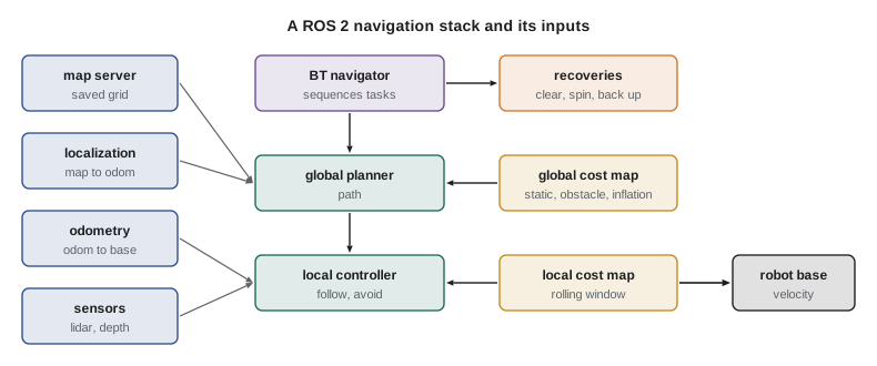
Nav2, the ROS 2 navigation framework (Macenski and colleagues, 2020), is representative of modern navigation stacks. It takes a map, a localization estimate (the transform from map to odom, from AMCL or slam_toolbox in localization mode), odometry (odom to base_link) and sensor data, and drives the robot to goals. Its main parts are a map server, a localizer, a global planner that computes a path through the map, a local controller that follows the path while avoiding obstacles at high rate, cost maps that represent obstacles for both, and a behavior-tree navigator that orchestrates them and handles failures. Each part is a plugin, so planners, controllers and recovery behaviors can be swapped.
Cost maps
A cost map turns the map and live sensor data into a grid of traversal costs. Nav2 builds cost maps from layers. The static layer copies the saved SLAM map. The obstacle layer (or a voxel layer for 3-D sensors) marks obstacles seen by sensors and clears cells that beams pass through, so people, pallets and open doors are represented as they are now. The inflation layer spreads cost outward from every obstacle: cells within the robot's inscribed radius are lethal, and cost then decays exponentially with distance, so planners prefer paths that keep a margin. Keep-out and speed-limit filters add areas that people mark by hand. The global cost map covers the whole map for planning; the local cost map is a small rolling window around the robot, updated at sensor rate, for the controller.
Cost maps are where localization errors become visible as navigation problems. If the localizer is off by 10 cm, the static layer's walls no longer line up with the live obstacle layer's walls, the corridor appears narrower, and the planner may report that the goal is unreachable. A well-tuned stack therefore watches the agreement between the static map and live scans as a health signal.
Worked problem
Inflation and narrow passages
A robot has an inscribed radius of 0.30 m. Its inflation layer marks cells within 0.30 m of an obstacle as lethal and adds decaying cost out to an inflation radius of 0.55 m. Can it plan through a 0.90 m doorway? What if localization error makes the doorway appear 0.80 m wide?
Show solution
- Lethal band from each side: 0.30 m, so the free center of a 0.90 m doorway is \( 0.90 - 0.60 = 0.30 \) m wide: passable, though every cell in it carries some inflation cost.
- At an apparent 0.80 m: free center \( 0.80 - 0.60 = 0.20 \) m, still passable, but all of it lies within the inflation radius of both sides, so costs are high.
- If error grew to make it appear 0.60 m, the lethal bands would meet and no path would exist.
Answer: Yes at 0.90 m and, with high cost, at 0.80 m. Localization error directly narrows apparent clearances, so the inflation radius and the localization accuracy must be chosen together.
Behavior trees and recovery
Nav2 sequences navigation with behavior trees, structures of action, condition and control nodes that are easier to extend and reason about than state machines. A typical tree computes a path, follows it, and replans at a fixed rate or when the path becomes blocked. When something fails, recovery behaviors run in a configured order: clear the cost maps (removing stale obstacles), spin in place (letting the sensors refresh and, if localization is uncertain, giving the particle filter new views), back up, or wait for a dynamic obstacle to move. If all recoveries fail, the navigator aborts and reports the failure to a higher-level task manager or fleet manager. Many localization problems surface as repeated recoveries, so recovery logs are a valuable diagnostic.
<!-- Excerpt of a Nav2 BT: navigate with replanning and recoveries -->
<root BTCPP_format="4" main_tree_to_execute="MainTree">
  <BehaviorTree ID="MainTree">
    <RecoveryNode number_of_retries="6" name="NavigateRecovery">
      <PipelineSequence name="NavigateWithReplanning">
        <RateController hz="1.0">
          <ComputePathToPose goal="{goal}" path="{path}" planner_id="GridBased"/>
        </RateController>
        <FollowPath path="{path}" controller_id="FollowPath"/>
      </PipelineSequence>
      <ReactiveFallback name="RecoveryFallback">
        <GoalUpdated/>
        <RoundRobin name="RecoveryActions">
          <ClearEntireCostmap service_name="local_costmap/clear_entirely_local_costmap"/>
          <Spin spin_dist="1.57"/>
          <Wait wait_duration="5"/>
          <BackUp backup_dist="0.30" backup_speed="0.05"/>
        </RoundRobin>
      </ReactiveFallback>
    </RecoveryNode>
  </BehaviorTree>
</root>
Map management
A deployed map has a life cycle. It is created during commissioning by a planned mapping run, cleaned (removing people and temporary objects captured during mapping, straightening walls if needed), annotated with keep-out zones, speed zones, docking stations and named goals, validated, and then versioned. Changes to the environment, such as new racking or a moved wall, require updating or re-mapping. For fleets, one master map is shared by all robots, so updates must be distributed consistently, and each robot's localizer must load the same version.
Large and multi-floor sites need more structure. Multi-floor operation keeps one map per floor and switches maps when the robot rides a lift, re-initializing localization at a known pose by the lift door. Very large sites split maps into tiles or submaps loaded as the robot moves. Outdoor robots often combine a local SLAM map with GNSS for global position, aligning the map frame to a geographic frame such as UTM.
Lifelong mapping addresses gradual change. Instead of freezing the map, the robot keeps updating it: slam_toolbox's lifelong mode adds new scans to the saved pose graph on later runs and removes old nodes whose scans no longer match, so the map tracks the environment while its size stays bounded. Research systems maintain multiple map versions per place (for example, door open and door closed) or model the probability that each part of the map changes, using frequency or time-of-day patterns. Dynamic objects should not be written into the long-term map at all; filtering detected people and vehicles before mapping keeps it clean.
Worked problem
When is a map out of date?
A warehouse robot's localizer reports, for each scan, the fraction of beam endpoints within 10 cm of a mapped obstacle. On the commissioning day the median was 0.85. Six weeks later, in aisle 14, it has fallen to 0.48, while elsewhere it remains above 0.80. What does this suggest, and what should happen?
Show solution
- A global fall would suggest a sensor or calibration problem; a local fall points to environmental change.
- Aisle 14's scans no longer match the map: racking has likely been moved or added.
- Flag the area, update the map there (lifelong mapping or a local re-map), and validate before returning robots to full speed.
Answer: The map is out of date in aisle 14. Monitoring scan-to-map agreement per area turns map maintenance from a reaction to failures into a routine task.
Evaluating SLAM and localization
Claims that a SLAM system is accurate need numbers, and the community has standard metrics, popularized by the TUM RGB-D benchmark (Sturm and colleagues, 2012) and the KITTI benchmark (Geiger and colleagues, 2012). Both compare an estimated trajectory with a ground-truth trajectory from a more accurate system, such as a motion-capture system indoors or RTK GNSS with an inertial navigation system outdoors.
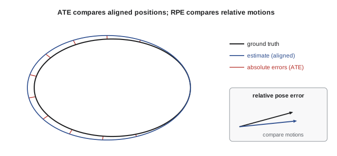
The absolute trajectory error (ATE) measures global consistency. First, the estimated trajectory is aligned to the ground truth with the best rigid transform (or a similarity transform for monocular systems), computed in closed form by the Umeyama method, which is the same SVD alignment as ICP with known correspondences. Then the error is the root-mean-square of the position differences:
The relative pose error (RPE) measures local accuracy, or drift: for each pair of poses a fixed interval apart (in time or distance), compare the estimated relative motion with the true relative motion. RPE is independent of where errors happened along the trajectory, which makes it the right metric for odometry; KITTI reports it as average translational error in percent over segments of 100 m to 800 m, and rotational error in degrees per meter. ATE is the right metric for the global map, because a single uncorrected loop can make ATE large even if RPE is small. The evo and rpg_trajectory_evaluation tools compute both.
import numpy as np
rng = np.random.default_rng(9)
t = np.linspace(0, 2 * np.pi, 200)
gt = np.column_stack([10 * np.cos(t), 6 * np.sin(t)])               # ground-truth loop
th = np.radians(5)
R0 = np.array([[np.cos(th), -np.sin(th)], [np.sin(th), np.cos(th)]])
drift = np.column_stack([np.linspace(0, 0.6, 200), np.linspace(0, -0.3, 200)])
est = (gt + drift + rng.normal(0, 0.05, gt.shape)) @ R0.T + [3.0, -2.0]   # rotated, shifted frame
def umeyama(src, dst):                                                # rigid alignment (no scale)
    ms, md = src.mean(0), dst.mean(0)
    U, S, Vt = np.linalg.svd((dst - md).T @ (src - ms))
    D = np.diag([1, np.sign(np.linalg.det(U @ Vt))])
    R = U @ D @ Vt; return R, md - R @ ms
R, tr = umeyama(est, gt)
aligned = est @ R.T + tr
ate = np.sqrt(np.mean(np.sum((aligned - gt) ** 2, 1)))
d = 20                                                                 # RPE over 20-pose intervals
rel_gt = gt[d:] - gt[:-d]; rel_est = aligned[d:] - aligned[:-d]
rpe = np.sqrt(np.mean(np.sum((rel_est - rel_gt) ** 2, 1)))
seg = np.mean(np.linalg.norm(rel_gt, axis=1))
print("ATE RMSE after alignment: %.3f m" % ate)
print("RPE RMSE over %d-pose segments (mean length %.2f m): %.3f m (%.2f %%)" % (d, seg, rpe, 100 * rpe / seg))
print("unaligned mean error would be: %.2f m" % np.mean(np.linalg.norm(est - gt, axis=1)))ATE RMSE after alignment: 0.200 m RPE RMSE over 20-pose segments (mean length 5.18 m): 0.129 m (2.48 %) unaligned mean error would be: 3.97 m
Worked problem
Interpreting ATE and RPE
System A has ATE 0.12 m and RPE 1.5 % on a 600 m run; system B has ATE 0.85 m and RPE 0.6 %. Which has better odometry, which has the better global map, and what might explain B?
Show solution
- Lower RPE means less local drift: B has better odometry.
- Lower ATE means better global consistency: A has the better map.
- B's low drift but large ATE suggests it missed or rejected loop closures, so its small drift accumulated uncorrected over 600 m.
Answer: B has better odometry, A the better map. A system needs both good odometry and reliable loop closure; the two metrics diagnose which part is weak.
Safety standards for mobile robots
Localization and mapping are not safety functions in themselves; standards require that collision avoidance and speed limits be enforced by safety-rated systems, typically safety laser scanners with configurable protective fields, that do not depend on SLAM being right.
In the US, ANSI/A3 R15.08-1 (2020) sets safety requirements for industrial mobile robots and R15.08-2 (2023) covers their integration into systems and applications, with ISO 3691-4 widely used for driverless industrial trucks and R15.06 for robot arms on mobile platforms. OSHA has no specific mobile robot standard, but its general duty clause and machinery rules apply, and the standards are used to show that hazards have been addressed.
Both countries' frameworks expect a risk assessment of the application, protective fields sized for the robot's stopping distance at each speed, and speed limits in shared areas, all independent of the navigation stack's software.
Common mistakes
MistakeTreating repeated recovery behaviors as a planner problem only
InsteadCheck localization first; misalignment between map and scans often causes them.
MistakeFreezing a map at commissioning and never checking it
InsteadMonitor scan-to-map agreement by area and update maps as the site changes.
MistakeReporting SLAM accuracy without aligning trajectories first
InsteadAlign with Umeyama (rigid, or similarity for monocular) before computing ATE.
MistakeUsing ATE alone to evaluate odometry
InsteadUse RPE for drift and ATE for global consistency.
MistakeRelying on SLAM for collision safety
InsteadUse safety-rated scanners and fields independent of the navigation software.
Summary and key terms
- A navigation stack combines a map, a localizer, odometry, planners, a controller, cost maps and a behavior-tree navigator.
- Cost maps layer the static map, live obstacles, inflation and hand-drawn filters for planning and control.
- Localization errors appear as narrowed clearances, unreachable goals and repeated recoveries.
- Maps have a life cycle: creation, cleaning, annotation, validation, versioning and updating.
- Multi-floor sites use one map per floor; lifelong mapping keeps maps current as the environment changes.
- ATE measures global consistency after alignment; RPE measures local drift.
- Collision safety must come from safety-rated systems following standards such as R15.08 and ISO 3691-4, not from SLAM.
- Nav2
- The ROS 2 navigation framework.
- Cost map
- A grid of traversal costs built from map and sensor layers.
- Inflation layer
- A cost map layer that spreads cost outward from obstacles.
- Behavior tree
- A hierarchical structure of nodes that sequences robot behaviors.
- Recovery behavior
- An action such as clearing cost maps or spinning, run when navigation fails.
- Lifelong mapping
- Continually updating a map across sessions as the environment changes.
- ATE
- Absolute trajectory error, measuring global consistency after alignment.
- RPE
- Relative pose error, measuring local drift over fixed intervals.
- Umeyama alignment
- Closed-form least-squares alignment of two point sets.
- Protective field
- A safety scanner zone that triggers a stop when entered.
Practice problems
Work each problem on paper first, then reveal the answer to check.
Which transform does a localizer publish in a ROS 2 navigation stack?
Show answer
map to odom.
Name three Nav2 cost map layers.
Show answer
Static, obstacle (or voxel) and inflation.
Inscribed radius 0.25 m, doorway 0.70 m: width of the lethal-free center?
Show answer
0.20 m.
Name two recovery behaviors.
Show answer
Clear cost maps, spin, back up or wait.
How is a multi-floor building usually mapped?
Show answer
One map per floor, linked through lifts.
What does slam_toolbox's lifelong mode remove?
Show answer
Old nodes whose scans no longer match.
What must be done before computing ATE?
Show answer
Align the estimated trajectory to ground truth.
Which metric suits odometry drift?
Show answer
RPE.
Low RPE but high ATE suggests what?
Show answer
Missing or rejected loop closures.
Should collision safety depend on SLAM?
Show answer
No; it should use safety-rated sensors and fields.
Lesson quiz · 5 questions
Score 60% or more to complete this lesson.
Create a free account to save your progress, take quizzes and earn a certificate.