
ENGG-130 · Lesson 5 of 5 · 39 min
Trusses
Look at a railway bridge, a roof over an arena, a transmission tower or the boom of a tower crane, and you will see the same pattern: slender straight members joined at their ends to form triangles. That is a truss. Trusses carry large loads over long spans with very little material, because every member is loaded only along its own axis, in pure tension or pure compression, which is the most efficient way to use steel or timber.
This chapter explains why trusses work, how to tell whether a truss can be analyzed by statics, and the two standard methods for finding member forces: the method of joints and the method of sections. It also shows how to spot members that carry no load, and finishes with frames and machines, structures whose members are not two-force members and must be taken apart piece by piece.
What makes a truss
A triangle is the only polygon that cannot change shape without changing the length of a side. Pin four bars into a square and it folds flat under a sideways push; add a diagonal and it becomes rigid. A truss is a structure built entirely from such triangles.
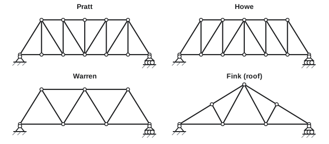
Different arrangements suit different jobs. In a Pratt truss under gravity load, the long diagonals are in tension and most of the shorter verticals are in compression, which suits steel, because long members in compression can buckle. A Howe truss reverses this, which suited the timber-and-iron bridges of the 1800s, when timber diagonals were good in compression and iron rods carried the tension. The Warren truss uses equilateral or isosceles triangles with no verticals. The Fink truss, with its W-shaped web, is what holds up most wood-frame house roofs in North America.
The top and bottom members are called chords, and the members between them make up the web. The points where members meet are joints (or panel points), and the space between adjacent verticals is a panel.
The modeling assumptions
Truss analysis rests on three assumptions:
- Members are connected at their ends by frictionless pins.
- Loads and reactions are applied only at the joints.
- The weight of each member is small compared with the loads, or is split equally between its two end joints.
Under these assumptions, every member has forces at only two points and no couples, so every member is a two-force member (Lesson 4). Its force acts along its own axis and is either tension (pulling on the joints, trying to stretch the member) or compression (pushing on the joints, trying to shorten it).
Real trusses are welded or bolted through gusset plates, not pinned, and their members do carry some bending. But because the members are slender and meet at a point, these secondary effects are usually small, and pin-jointed analysis gives member forces within a few percent. Floor and roof loads reach the joints through a deck and floor beams that sit on the panel points, which is why the second assumption holds in practice.
Is the truss determinate?
Each joint is a particle in equilibrium, giving two equations, so a planar truss with \(j\) joints gives \(2j\) equations. The unknowns are the \(m\) member forces plus the \(r\) support reactions. Comparing:
With the usual pin and roller (\(r = 3\)), a determinate simple truss has \(m = 2j - 3\). The count is necessary but not sufficient: the members must also be arranged in triangles so that no part of the truss can move as a mechanism. A truss built by starting with one triangle and adding two members and one joint at a time (a simple truss) always passes both tests.
Worked problem
Checking determinacy
A bridge truss has 8 joints and 13 members, supported by a pin and a roller. Is it determinate?
Show solution
- Unknowns: \(m + r = 13 + 3 = 16\).
- Equations: \(2j = 16\).
Answer: Yes. 16 unknowns and 16 equations, and the truss is built from triangles, so it is statically determinate
The method of joints
The method of joints treats each joint as a particle and applies \(\sum F_x = 0\) and \(\sum F_y = 0\). Because each joint gives only two equations, you must start at a joint with no more than two unknown member forces, usually a support, after finding the reactions from the equilibrium of the whole truss.
A sign convention keeps the bookkeeping clean: assume every unknown member is in tension, which means drawing its force pulling away from the joint. A positive answer is tension (T); a negative answer is compression (C). Carry the sign forward: at the next joint, a member already found to be −37.5 kN is still drawn pulling away, with the value −37.5 substituted.
Worked problem
Pratt truss by the method of joints
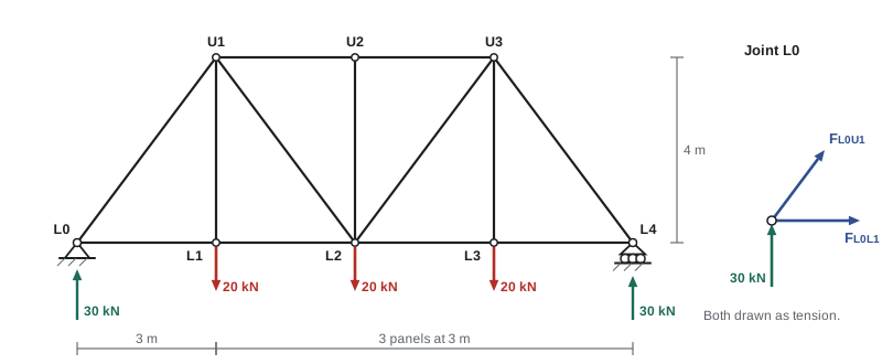
The Pratt truss shown spans 12 m in four 3 m panels and is 4 m deep. Joints L1, L2 and L3 on the bottom chord each carry 20 kN. Find the forces in members L0U1, L0L1, U1L1, U1U2 and U1L2.
Show solution
- Reactions: by symmetry, each support carries half of the 60 kN, so \(L0_y = L4_y = 30\) kN. There are no horizontal loads, so \(L0_x = 0\).
- Joint L0: unknowns \(F_{L0U1}\) (along a 3-4-5 slope, up and to the right) and \(F_{L0L1}\) (to the right).
- \[\sum F_y = 30 + 0.8F_{L0U1} = 0 \;\Rightarrow\; F_{L0U1} = -37.5 \text{ kN}\]
- \[\sum F_x = F_{L0L1} + 0.6F_{L0U1} = 0 \;\Rightarrow\; F_{L0L1} = +22.5 \text{ kN}\]
- Joint L1: the bottom chords are collinear, so vertical equilibrium gives \(F_{U1L1} - 20 = 0\), so \(F_{U1L1} = +20\) kN, and \(F_{L1L2} = F_{L0L1} = 22.5\) kN.
- Joint U1: the end post L0U1 (−37.5) pulls toward L0 with components \(-37.5(-0.6, -0.8) = (22.5, 30)\). The vertical U1L1 (+20) pulls down. The unknowns are \(F_{U1U2}\) (toward U2) and \(F_{U1L2}\) (toward L2, direction (0.6, −0.8)).
- \[\sum F_y = 30 - 20 - 0.8F_{U1L2} = 0 \;\Rightarrow\; F_{U1L2} = +12.5 \text{ kN}\]
- \[\sum F_x = 22.5 + F_{U1U2} + 0.6(12.5) = 0 \;\Rightarrow\; F_{U1U2} = -30.0 \text{ kN}\]
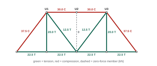
Answer: L0U1 = 37.5 kN (C), L0L1 = 22.5 kN (T), U1L1 = 20.0 kN (T), U1U2 = 30.0 kN (C), U1L2 = 12.5 kN (T)
The pattern is typical of a truss carrying gravity load. The top chord is in compression and the bottom chord in tension, just like the top and bottom of a bent beam. In fact a truss is a beam with the unneeded material removed: the chords do the job of the flanges and the web members do the job of the web.
Zero-force members
Some members carry no force under a particular loading. Spotting them first saves work and avoids errors. Two rules, both from equilibrium of a single joint:
- If only two non-collinear members meet at a joint with no external load or support, both are zero-force members.
- If three members meet at an unloaded joint and two of them are collinear, the third member is a zero-force member.
In the Pratt truss, joint U2 is unloaded and has two collinear top chords plus the vertical U2L2. By the second rule, \(F_{U2L2} = 0\).
Zero-force members are not useless. They brace compression members against buckling by cutting their unsupported length in half, they keep the truss stable during construction, and they pick up load when the loading changes. Under a single moving vehicle, or a wind load, U2L2 would carry force. Engineers design every member for the worst of many load cases.
The method of sections
If you need the force in one member in the middle of a large truss, working joint by joint from the support is slow. The method of sections goes straight to it. Cut the truss into two pieces with an imaginary line that passes through the member you want, cutting no more than three members whose forces are unknown. Then apply the three equilibrium equations to either piece.
The trick is to choose moment points well. Take moments about the point where two of the cut members intersect; those two drop out, leaving one equation in the third.
Worked problem
Method of sections
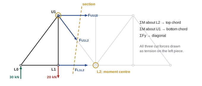
Use a section through the second panel of the Pratt truss to find the forces in U1U2, L1L2 and U1L2 directly.
Show solution
- Cut through U1U2, U1L2 and L1L2 and keep the left piece. On it act the 30 kN reaction at L0, the 20 kN load at L1 and the three member forces, each drawn as tension (pulling away from the cut piece).
- Moments about L2 (at x = 6 m), where U1L2 and L1L2 meet. Counterclockwise positive: the reaction gives \(-30(6)\), the load at L1 gives \(+20(3)\), and the top chord force, acting toward U2 at 4 m above L2, gives \(-4F_{U1U2}\).
- \[-180 + 60 - 4F_{U1U2} = 0 \;\Rightarrow\; F_{U1U2} = -30.0 \text{ kN}\]
- Moments about U1 (x = 3 m, y = 4 m), where U1U2 and U1L2 meet: the reaction gives \(-30(3)\), the load at L1 lies directly below U1 and gives nothing, and the bottom chord force at 4 m below U1 gives \(+4F_{L1L2}\).
- \[-90 + 4F_{L1L2} = 0 \;\Rightarrow\; F_{L1L2} = +22.5 \text{ kN}\]
- Vertical forces (the chords are horizontal, so only the diagonal has a vertical part): \(30 - 20 - 0.8F_{U1L2} = 0\), so \(F_{U1L2} = +12.5\) kN.
Answer: U1U2 = 30.0 kN (C), L1L2 = 22.5 kN (T), U1L2 = 12.5 kN (T), matching the method of joints, with three equations instead of nine
The vertical-force equation in that example reveals something useful. The net vertical force on the left piece, \(30 - 20 = 10\) kN, is the shear force in that panel, and in a truss with horizontal chords the diagonal is the only member that can carry it. The moment about L2, 120 kN·m, is the bending moment at that point, carried by the couple between the chords: \(30 \text{ kN} \times 4 \text{ m} = 120\) kN·m. Deeper trusses therefore have smaller chord forces, which is why long-span trusses are deep.
Choosing a method
- All member forces wanted: method of joints, starting from a support.
- One or two members in the middle of a large truss: method of sections.
- Both are often combined: sections to reach the middle quickly, joints to finish nearby members.
In professional practice, trusses are analyzed by computer using the matrix stiffness method, which solves the same joint equilibrium equations all at once. Hand methods remain essential for checking computer output: an engineer who seals a design is responsible for the results, whatever software produced them.
Why compression members matter
A tension member fails when the material yields or breaks, so its strength depends only on its cross-sectional area. A compression member can fail at a much lower load by buckling: bowing sideways and collapsing. Long slender compression members are weak, which is why designers keep them short (by adding bracing members, often the "zero-force" ones), make them stockier, or choose a truss form, like the Pratt, that puts the long members in tension.
The first Quebec Bridge, which you met in ENGG-100, collapsed in 1907 when a built-up lower chord member in the south anchor arm, next to the main pier, buckled. The chord forces had been calculated, but the member's self-weight had been underestimated and the design of its lacing (the light bracing that ties the parts of a built-up member together) was inadequate for the compression it carried. Statics gives the member forces; the next courses in mechanics of materials and steel design teach how to make members that can carry them.
Frames and machines
Not every structure is a truss. In a frame (a structure that stays put) or a machine (one that transmits forces and moves), at least one member is a multi-force member: it has forces at three or more points, or carries loads along its length. Its forces are not along its axis, so the shortcuts of truss analysis do not apply.
The method is to take the structure apart. Draw a free-body diagram of each member separately, showing the pin forces as unknown components. Where two members share a pin, the forces they exert on each other are equal and opposite (Newton's third law), so use the same symbols with opposite directions on the two diagrams. Identify any two-force members first, since each adds only one unknown. Then write three equations for each multi-force member.
Worked problem
A stepladder
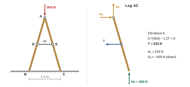
A stepladder has two 2.5 m legs, AB and AC, hinged at the top A, 2.4 m above a smooth floor, with the feet 1.4 m apart. A horizontal tie joins the midpoints D and E of the legs. An 800 N person stands at the top. Find the tension in the tie and the force at the hinge. Neglect the ladder's weight.
Show solution
- Whole ladder: the floor is smooth, so the reactions are vertical. By symmetry \(N_B = N_C = 400\) N.
- Apply the 800 N load to the hinge pin itself, and analyze leg AC alone. Its forces: \(N_C = 400\) N up at C, the tie tension \(T\) pulling toward D at E, and the hinge force components \(A_x, A_y\) at A.
- Coordinates from A: C is at (0.7, −2.4) m and E at (0.35, −1.2) m.
- Moments about A eliminate the hinge force. With \(M = xF_y - yF_x\): from \(N_C\), \(0.7(400) = 280\) N·m; from the tie, force \((-T, 0)\) at E, \(-(-1.2)(-T) = -1.2T\).
- \[280 - 1.2T = 0 \;\Rightarrow\; T = 233 \text{ N}\]
- \(\sum F_x = 0\): \(A_x - 233 = 0\), so \(A_x = 233\) N, pushing the leg outward. \(\sum F_y = 0\): \(A_y + 400 = 0\), so \(A_y = -400\) N: the hinge pushes down on leg AC.
Answer: The tie carries 233 N in tension. At the hinge, each leg receives 233 N horizontally and 400 N downward, a resultant of 463 N. Without the tie, the smooth floor could not stop the feet from sliding apart
Worked problem
Pliers
A hand squeezes the handles of a pair of pliers with 150 N on each, 100 mm from the pivot. The jaws grip a wire 25 mm from the pivot. Find the gripping force and the force on the pivot pin.
Show solution
- Take one half of the pliers (a multi-force member: hand force, jaw force, pin force). Moments about the pin: \(150(100) = F_{jaw}(25)\), so \(F_{jaw} = 600\) N.
- Force balance on the half (all three forces are parallel): the pin force is \(150 + 600 = 750\) N.
Answer: The jaws grip with 600 N, a mechanical advantage of 4, and the pin carries 750 N. The pin must be designed for the largest force in the tool, not the hand force
Common mistakes
MistakeStarting the method of joints at a joint with three or more unknowns.
InsteadFind the reactions first, then start at a joint with at most two unknown members, usually a support.
MistakeMixing up the direction convention partway through.
InsteadDraw every unknown as tension (away from the joint). Positive means T, negative means C, and keep the sign when using the value at the next joint.
MistakeCutting four or more unknown members with a section.
InsteadA section gives three equations. Cut at most three members with unknown forces, and not all three meeting at one point.
MistakeTreating every member of a frame as a two-force member.
InsteadCheck each member: if it has forces at more than two points or loads along its length, its pin forces are not along its axis.
MistakeAssuming a zero-force member can be removed.
InsteadIt carries no load in this case only. It braces other members and carries load under other loadings.
MistakeUsing m = 2j − 3 alone to decide that a truss is stable.
InsteadThe count must match, and the members must form a rigid pattern of triangles.
Summary and key terms
- A truss is a structure of straight members forming triangles, pinned at the ends and loaded at the joints, so every member is a two-force member in tension or compression.
- A planar truss is determinate when m + r = 2j and its members form a rigid arrangement.
- Method of joints: find reactions, then apply ΣFx = 0 and ΣFy = 0 at each joint, starting where only two unknowns meet. Assume tension; negative means compression.
- Zero-force members occur at unloaded joints with two non-collinear members, or with three members where two are collinear.
- Method of sections: cut through at most three unknown members and take moments where two of them meet.
- Under gravity load, top chords are usually in compression and bottom chords in tension; deeper trusses have smaller chord forces.
- Frames and machines contain multi-force members. Take them apart, use equal and opposite pin forces, and write three equations per member.
- Truss
- A structure of slender members joined at their ends to form triangles.
- Chord
- A top or bottom member running the length of a truss.
- Web member
- A vertical or diagonal member between the chords.
- Joint (panel point)
- A point where truss members meet and loads are applied.
- Gusset plate
- A steel plate that connects members at a joint.
- Simple truss
- A truss built from a triangle by adding two members and one joint at a time.
- Method of joints
- Finding member forces from the equilibrium of each joint as a particle.
- Method of sections
- Finding member forces from the equilibrium of a piece cut from the truss.
- Zero-force member
- A member that carries no force under a particular loading.
- Buckling
- Sideways collapse of a slender compression member.
- Frame
- A structure containing at least one multi-force member.
- Machine
- A frame with moving parts that transmits and changes forces.
Practice problems
Work each problem on paper first, then reveal the answer to check.
A truss has 11 members and 7 joints with a pin and a roller. Is it determinate?
Show answer
m + r = 14 = 2j. Determinate, if the members form triangles.
A triangular truss ABC has A and B 6 m apart on a pin and roller, and apex C 4 m above the midpoint. A 24 kN load acts down at C. Find the member forces.
Show answer
Reactions 12 kN each. At A: AC slope (3, 4)/5. 0.8F_AC + 12 = 0, F_AC = −15 kN (C). F_AB + 0.6(−15) = 0, F_AB = 9 kN (T). By symmetry F_BC = 15 kN (C).
In the Pratt truss example, find the force in U3L3 and U3L2 using symmetry, and confirm by the method of joints at L3.
Show answer
U3L3 = 20 kN (T) and U3L2 = 12.5 kN (T) by symmetry. At L3: vertical equilibrium F_U3L3 − 20 = 0. ✓
If the Pratt truss also carried a 10 kN load at U2, what would the force in U2L2 be?
Show answer
At joint U2, the top chords are horizontal, so vertical equilibrium gives −10 − F_U2L2 = 0, so F_U2L2 = −10 kN (C). The vertical pushes the load down to L2.
A joint J has only two members, JA horizontal and JB vertical, and carries no load or support. What are the member forces?
Show answer
ΣFx = 0 gives F_JA = 0 and ΣFy = 0 gives F_JB = 0. Both are zero-force members.
For the Pratt truss with all three loads increased to 30 kN, what is the force in the end post L0U1?
Show answer
Reactions 45 kN. F = −45/0.8 = −56.25 kN, so 56.3 kN (C). Forces scale with the loads.
If the Pratt truss were 3 m deep instead of 4 m (same 3 m panels), what would the top chord force U1U2 be?
Show answer
Moments about L2 are unchanged at 120 kN·m. F = −120/3 = −40 kN (C). A shallower truss has larger chord forces.
A Howe truss has the same geometry as the example but with diagonals L0U1, L1U2, U2L3, U3L4. Under the same loads, is the diagonal L1U2 in tension or compression? Find it with a section through panel 2.
Show answer
Cut L1L2, L1U2 and U1U2. Vertical: 30 − 20 + 0.8F = 0 (L1U2 runs up and to the right from L1), so F = −12.5 kN: compression, as expected for a Howe truss.
In the stepladder example, the tie is moved down to 0.6 m above the floor (one quarter of the way up each leg). Find the new tie tension.
Show answer
E is now at (0.525, −1.8) from A. ΣM_A: 0.7(400) − 1.8T = 0, so T = 156 N. A lower tie needs less force.
A pair of bolt cutters has handles 600 mm long from the pivot and jaws 20 mm from the pivot. What jaw force does 200 N on each handle produce?
Show answer
F = 200 × 600/20 = 6000 N. Real bolt cutters use a compound linkage to get even more.
Lesson quiz · 5 questions
Score 60% or more to complete this lesson.
Create a free account to save your progress, take quizzes and earn a certificate.