
PHYS-130 · Lesson 9 of 12 · 32 min
Equilibrium, stability and elasticity
Most of engineering is about things that should not move: buildings, bridges, cranes on their outriggers, ladders against walls, machine frames on their foundations. Lesson 8 introduced torque and the rotational form of Newton's second law. Setting the accelerations to zero gives the conditions for a rigid body to stay at rest, and this lesson applies them to the questions engineers ask first: where is the center of gravity, what loads does each support carry, how much load will tip a crane, and when will a ladder slip? It then drops the assumption that bodies are perfectly rigid. Real materials stretch, compress and shear under load, and the ideas of stress, strain and elastic modulus describe how much, leading to the deformation of rods and cables and to the stresses caused by temperature change. ENGG-130 develops equilibrium analysis fully; this lesson lays the physical foundations.
The conditions for equilibrium
A rigid body is in static equilibrium when it has no linear or angular acceleration. From \(\sum\mathbf{F} = m\mathbf{a}\) and \(\sum\boldsymbol{\tau} = I\boldsymbol{\alpha}\) (Lesson 8), this requires
For forces in a plane, these give three scalar equations: \(\sum F_x = 0\), \(\sum F_y = 0\) and \(\sum\tau = 0\) about any point. Because the net force is zero, the net torque is the same about every point, so choose the point that eliminates the most unknowns, usually where an unknown force acts. Three independent equations can determine at most three unknown support forces; structures with more supports than that are statically indeterminate and need the deformation analysis of later courses.
The method follows the free-body procedure of Lesson 3: isolate the body, draw every external force including support reactions (with assumed directions), write the three equations and solve. A negative answer simply means the force acts opposite to the direction assumed.
Center of gravity
The weight of a body acts as if concentrated at its center of gravity. In a uniform gravitational field this is the same as the center of mass (Lesson 7), found for a system of parts by weighting each part's position by its weight: \(x_{cg} = \sum W_ix_i/\sum W_i\). For a uniform body it lies at the geometric center. Knowing it is essential for lifting (a load hangs with its center of gravity directly below the hook), for vehicle stability and for distributing loads on supports.
Worked problem
Reactions on a loaded beam
A 6.0 m uniform beam weighing 2.0 kN rests on supports at its ends, A and B. A 9.0 kN motor sits 2.0 m from A. Find the support reactions.
Show solution
- Torques about A (counterclockwise positive): \(6.0R_B - 2.0 \times 3.0 - 9.0 \times 2.0 = 0\), so \(R_B = 24/6.0 = 4.0\) kN.
- Vertical forces: \(R_A + R_B - 2.0 - 9.0 = 0\), so \(R_A = 7.0\) kN.
- Check, torques about B: \(-6.0R_A + 2.0 \times 3.0 + 9.0 \times 4.0 = -42 + 6 + 36 = 0\). ✓
Answer: R_A = 7.0 kN and R_B = 4.0 kN. The support nearer the heavy load carries more of it. Checking with a second torque equation costs a moment and catches most arithmetic slips.
Stability and tipping
A body resting on a base is stable as long as the line of action of its total weight, together with any applied loads, passes inside the base. When the combined loads move the resultant to the edge of the base, the support force there becomes the only one, and any further load tips the body over that edge. Stability is improved by a wide base and a low center of gravity, which is why cranes use outriggers and counterweights and why tall cabinets are anchored to walls.
Worked problem
A mobile crane's tipping load
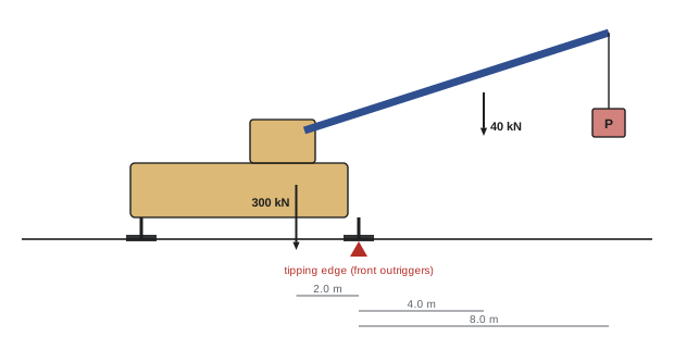
A mobile crane on outriggers weighs 300 kN, with its center of gravity 2.0 m behind the front outriggers. Its boom weighs 40 kN, acting 4.0 m in front of them, and the load hangs 8.0 m in front. What load will just tip the crane?
Show solution
- At tipping, the rear outriggers lift off, so take torques about the front outriggers.
- Restoring torque: \(300 \times 2.0 = 600\) kN·m. Overturning torque: \(40 \times 4.0 + 8.0P\).
- Tipping when \(160 + 8.0P = 600\): P = 55 kN.
Answer: The crane tips at a load of 55 kN (about 5.6 t) at this radius. Crane load charts set rated loads well below the tipping load, and they fall quickly as the radius increases because the overturning arm grows. Most crane overturns happen when the radius is increased with the load attached, outriggers are not fully extended, or the ground under an outrigger gives way.
Friction and equilibrium: the ladder
Friction often keeps a structure in equilibrium, and the question becomes how close it is to slipping. The leaning ladder is the classic example, and a real hazard: falls from ladders are one of the commonest causes of serious injury at work.
Worked problem
How high can you climb?
A 5.0 m ladder of mass 20 kg leans against a smooth wall at 60° to the ground. The coefficient of static friction at the floor is 0.40. How far up the ladder can an 80 kg worker climb before it slips? What changes at 65° and at 75.5°?
Show solution
- Forces: weights at the ladder midpoint and at distance d along it; floor normal N and friction f; a horizontal wall force \(F_w\) (no friction at the smooth wall).
- Vertical: \(N = 100 \times 9.81 = 981\) N. Horizontal: \(f = F_w\), and at the point of slipping \(f = 0.40N = 392\) N.
- Torques about the foot: \(F_w(5.0\sin 60°) = 196(2.5\cos 60°) + 785\,d\cos 60°\), so \(1699 = 245 + 392d\) and d = 3.7 m.
- Repeating at 65° gives d = 4.7 m; at 75.5°, the solution exceeds the ladder length, so the worker can reach the top.
Answer: At 60° the ladder slips when the worker is 3.7 m up; at 65°, 4.7 m; at 75.5° it does not slip at all. That angle is the familiar "1 out for every 4 up" rule taught in ladder safety training (HSE-213): a steeper ladder needs much less friction at its foot, because the wall force needed to balance the torques shrinks.
Stress and strain
No real body is perfectly rigid. A rod pulled by a force F stretches; how much depends on its size and material. To separate the two, engineers use stress, force per unit area, and strain, the fractional change in length:
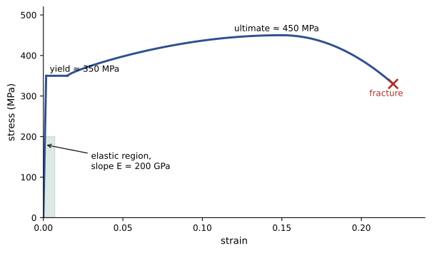
Stress is measured in pascals (N/m²), usually megapascals (MPa, equal to N/mm²); strain is dimensionless. For most materials under modest loads, stress is proportional to strain (Hooke's law for materials), with the elastic modulus, or Young's modulus, E as the constant:
Typical values of E are 200 GPa for steel, 70 GPa for aluminum, 25 to 35 GPa for concrete, 10 to 14 GPa for timber along the grain and 1 to 3 GPa for many plastics. The rod behaves as a spring of stiffness k = AE/L (Lesson 4). Proportionality holds up to the yield strength (about 250 to 350 MPa for structural steel), beyond which the material deforms permanently; designs keep working stresses well below yield.
Worked problem
A hanger rod
A steel hanger rod 12 mm in diameter and 3.0 m long carries 20 kN. Find the stress and the elongation (E = 200 GPa).
Show solution
- Area: \(\pi \times 6^2 = 113\) mm².
- Stress: \(20\,000/113 = 177\) MPa.
- Strain: \(177/200\,000 = 8.8 \times 10^{-4}\); elongation \(8.8 \times 10^{-4} \times 3000 = 2.7\) mm.
Answer: A stress of 177 MPa, safely below the yield strength of common rod steel with a reasonable margin, and an elongation of 2.7 mm. If the rod supported one end of a floor beam, this stretch would show up as a small sag, which designers check alongside strength.
Shear, bulk and thermal stress
Forces can also shear a body, sliding one face relative to the opposite face, as in a bolt holding two plates or an earthquake bearing. Shear stress τ = F/A produces a shear strain (angle) γ, with \(\tau = G\gamma\), where G is the shear modulus (about 80 GPa for steel). Pressure applied equally on all sides changes volume, described by the bulk modulus \(B = -\Delta p/(\Delta V/V)\): about 2.2 GPa for water, which is why water is often treated as incompressible, and why the pressure surge from suddenly closing a valve in a long pipeline (water hammer) can be so large.
Temperature changes also cause strain. A bar heated by ΔT expands by \(\Delta L = \alpha L\,\Delta T\), with a coefficient of thermal expansion α of about 12 × 10⁻⁶ per kelvin for steel and 10 to 12 × 10⁻⁶ for concrete. If the bar is free, this causes no stress. If it is prevented from expanding, the restraint must push back with exactly the force needed to compress it by that amount, giving a thermal stress:
Worked problem
Continuously welded rail
Continuously welded rail is laid and anchored at 25 °C. Find the stress on a 0 °C winter night and on a 50 °C summer afternoon, taking E = 200 GPa and α = 12 × 10⁻⁶ /K.
Show solution
- For a 25 K change: \(\sigma = 200\,000 \times 12 \times 10^{-6} \times 25 = 60\) MPa.
- Cold: 60 MPa in tension (the rail wants to shorten). Hot: 60 MPa in compression.
Answer: 60 MPa either way. Rails are anchored at a "neutral" temperature chosen near the middle of the expected range so neither extreme is too severe; in a heat wave, compression can make track buckle sideways ("sun kinks"), and in extreme cold, tension can break rails or welds. Bridges, pipelines and building facades use expansion joints and loops to avoid such stresses.
Common mistakes
MistakeForgetting a support reaction or the body's own weight on the free-body diagram.
InsteadInclude every external force: loads, weight and all reactions.
MistakeTaking torques about an awkward point.
InsteadChoose the point where unknown forces act to eliminate them.
MistakeAssuming a load can increase until a support breaks.
InsteadCheck tipping: the resultant must stay inside the base.
MistakeConfusing stress (force per area) with force.
InsteadDivide by the cross-sectional area; compare stress with material strength.
MistakeIgnoring thermal stress in restrained members.
InsteadA restrained member develops σ = EαΔT; provide joints or design for it.
Summary and key terms
- Static equilibrium requires ΣF = 0 and Στ = 0; in a plane, three equations for at most three unknowns.
- The center of gravity is where the weight acts; x_cg = ΣWᵢxᵢ/ΣWᵢ.
- A body tips when the resultant load reaches the edge of its base; cranes have rated loads well below tipping.
- Friction keeps ladders in place; steeper ladders (about 75°) need much less friction.
- Stress σ = F/A, strain ε = ΔL/L, and σ = Eε in the elastic range, so ΔL = FL/(AE).
- Shear modulus G and bulk modulus B describe shear and volume changes.
- A restrained member heated or cooled by ΔT develops thermal stress EαΔT.
- Static equilibrium
- A state of zero linear and angular acceleration.
- Support reaction
- A force exerted on a body by a support.
- Statically indeterminate
- Having more unknown supports than the equilibrium equations can determine.
- Center of gravity
- The point at which the total weight of a body acts.
- Tipping load
- The load at which a body begins to overturn about the edge of its base.
- Stress
- Internal force per unit area.
- Strain
- Fractional change in length.
- Young's modulus
- The ratio of stress to strain in the elastic range.
- Yield strength
- The stress beyond which a material deforms permanently.
- Thermal stress
- Stress caused by preventing thermal expansion or contraction.
Practice problems
Work each problem on paper first, then reveal the answer to check.
A 4 m beam on end supports carries 12 kN at 1 m from support A. Find the reactions (neglect beam weight).
Show answer
R_A = 9 kN, R_B = 3 kN.
Masses of 2 kg at x = 0, 3 kg at x = 1 m and 5 kg at x = 2 m: where is the center of gravity?
Show answer
(0 + 3 + 10)/10 = 1.3 m.
In the crane example, what is the tipping load at a radius of 10 m?
Show answer
(600 − 160)/10 = 44 kN.
A uniform 500 N box, 0.6 m wide and 1.8 m tall, is pushed horizontally at its top edge. Ignoring sliding, what force tips it?
Show answer
Torques about the far bottom edge: 500 × 0.3 = 1.8F, so F = 83 N.
What angle does the 4-to-1 ladder rule give?
Show answer
arctan 4 = 75.5°.
An aluminum rod (E = 70 GPa) 2 m long with area 100 mm² carries 7 kN. Find its elongation.
Show answer
7000 × 2000/(100 × 70 000) = 2.0 mm.
Find the stiffness k = AE/L of that rod.
Show answer
3.5 MN/m.
A steel cable has a working stress limit of 400 MPa. What area is needed for 100 kN?
Show answer
250 mm².
A restrained concrete slab (E = 30 GPa, α = 10 × 10⁻⁶/K) cools by 20 K. Find the thermal stress.
Show answer
6 MPa tension, enough to crack unreinforced concrete; hence control joints.
By how much does a 100 m steel bridge expand for a 50 K rise?
Show answer
12 × 10⁻⁶ × 100 × 50 = 0.06 m (60 mm).
Lesson quiz · 5 questions
Score 60% or more to complete this lesson.
Create a free account to save your progress, take quizzes and earn a certificate.