
PHYS-131 · Lesson 8 of 12 · 26 min
Inductance, magnetic energy and magnetic materials
Lesson 7 showed that a changing magnetic flux induces an emf, the principle of generators and transformers. A coil carrying a changing current is itself in a changing field of its own making, so it induces an emf in itself that opposes the change. This property, inductance, is to current what mass is to velocity: it resists sudden change. It explains why relays and motors produce dangerous voltage spikes when switched off, how energy is stored in magnetic fields, why transformer cores are laminated, and why electrical systems use inductors to smooth current and filter noise. This lesson develops self- and mutual inductance, the energy stored in an inductor and in a magnetic field, the transient behavior of RL circuits, eddy currents, and the magnetic materials (soft iron, electrical steel and permanent magnets) on which motors, transformers and generators depend.
Self-inductance
A current I in a coil of N turns produces a magnetic flux Φ through each turn. The self-inductance L is the total flux linkage per unit current:
measured in henries (H = Wb/A = V·s/A). By Faraday's law (Lesson 7), a changing current then induces an emf in the coil itself:
The minus sign (Lenz's law) says the induced emf opposes the change: it pushes back against a rising current and tries to keep a falling one going. For a long solenoid of N turns, length ℓ and cross-sectional area A, the field is \(B = \mu_0NI/\ell\) (Lesson 7), so
Inductance grows with the square of the number of turns, and filling the coil with iron or ferrite multiplies it by the material's relative permeability, often by hundreds or thousands.
Worked problem
An air-core coil
A solenoid has 500 turns wound on a 0.25 m long former of radius 20 mm. Find its inductance, and the emf induced when its current rises at 100 A/s.
Show solution
- Area: \(\pi \times 0.02^2 = 1.26 \times 10^{-3}\) m².
- \(L = 4\pi \times 10^{-7} \times 500^2 \times 1.26 \times 10^{-3}/0.25 = 1.58 \times 10^{-3}\) H.
- Induced emf: \(1.58 \times 10^{-3} \times 100 = 0.158\) V, opposing the rise.
Answer: About 1.6 mH and 0.16 V. Adding a ferrite core with an effective relative permeability of 200 would raise L to about 0.3 H in the same space, which is why practical inductors use magnetic cores.
Energy stored in an inductor
Building up a current against the opposing emf takes work: at each instant the source supplies power \(\mathcal{E}I = LI\,dI/dt\). Integrating from zero to the final current gives the energy stored:
the magnetic counterpart of the capacitor's \(\tfrac{1}{2}CV^2\) (Lesson 4). The energy resides in the magnetic field itself, with an energy density
Strong fields store a lot of energy. In a 3 T MRI magnet, \(u_B = 9/(2 \times 4\pi \times 10^{-7}) = 3.6 \times 10^6\) J/m³; with several cubic meters of high field, the stored energy is in the megajoules, which is why a superconducting magnet must be able to dump its energy safely if it loses superconductivity (a "quench").
RL circuits
When a voltage V is switched onto a resistance R in series with an inductance L, the current cannot jump. Kirchhoff's voltage law gives \(V = IR + L\,dI/dt\), a first-order equation (MATH-201) with solution
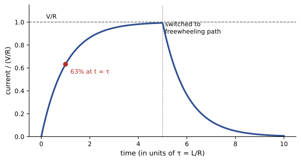
The current rises toward V/R with time constant τ = L/R, reaching 63% after one time constant and over 99% after five, exactly like the voltage on a charging capacitor (Lesson 4) but with the roles of current and voltage exchanged. If the source is removed and the coil is connected across a resistance, the current decays as \(e^{-t/\tau}\).
Switching off an inductor
Opening a switch in series with an inductor tries to stop its current almost instantly. Since \(\mathcal{E} = -L\,dI/dt\), a very rapid decrease produces a very large voltage, enough to arc across the switch contacts or destroy a transistor. This inductive kick is put to use in automotive ignition coils, which generate tens of kilovolts from a 12 V battery, and in boost converters. Everywhere else it must be controlled: relay and solenoid coils are fitted with a freewheeling (flyback) diode across them, which gives the current a path to decay gently through the coil's own resistance.
Worked problem
A relay coil
A relay coil has L = 0.20 H and R = 100 Ω and runs from 12 V. Find the steady current, the time constant and the stored energy. If the transistor driving it switches off in 1 µs with no protection, estimate the induced voltage.
Show solution
- Steady current: 12/100 = 0.12 A. Time constant: 0.20/100 = 2.0 ms.
- Energy: \(\tfrac{1}{2} \times 0.20 \times 0.12^2 = 1.44\) mJ.
- Unprotected switch-off: \(\mathcal{E} \approx L\,\Delta I/\Delta t = 0.20 \times 0.12/10^{-6} = 24\,000\) V.
Answer: The coil pulls in about 10 ms after switch-on (5τ) and stores 1.4 mJ. Switching it off abruptly would try to produce around 24 kV; in practice the transistor breaks down first and is destroyed. A flyback diode limits the voltage to under a volt above the supply and lets the 1.4 mJ dissipate in the coil resistance in a few milliseconds.
LC circuits and electrical oscillation
Connect a charged capacitor across an inductor and something familiar happens. The capacitor discharges through the inductor, building up a current and transferring its electric energy into the inductor's magnetic field. The inductor then keeps the current flowing after the capacitor is empty, charging it with the opposite polarity, and the process reverses. Energy oscillates between \(\tfrac{1}{2}CV^2\) and \(\tfrac{1}{2}LI^2\), exactly as it moves between potential and kinetic energy in a mass on a spring (PHYS-130), with L playing the role of mass and 1/C the role of stiffness. Kirchhoff's voltage law gives \(L\,d^2q/dt^2 + q/C = 0\), the simple harmonic equation, with natural frequency
A 10 mH inductor with a 1 µF capacitor oscillates at 1.59 kHz. Resistance damps the oscillation, just as friction damps a spring. LC circuits set the frequency of radio transmitters and receivers, and Lesson 9 shows how they behave when driven by an AC source at or near this frequency: resonance.
Inductors in practice
Practical inductors appear wherever current must be smoothed or limited. Switch-mode power supplies use an inductor to store energy during each switching cycle and release it to the load, which is how a laptop adapter converts mains voltage efficiently. DC chokes smooth the rectified current in variable-speed drives, line reactors limit the inrush and harmonic currents drawn by large drives, and current-limiting reactors restrict fault currents in power systems. Each must be rated not only for its inductance but for the current it carries without saturating its core or overheating its winding, and for the voltage it must withstand when the current changes quickly.
Mutual inductance
When the changing current in one coil sends flux through a second coil, it induces an emf there: \(\mathcal{E}_2 = -M\,dI_1/dt\), where M is the mutual inductance, which depends on the geometry and on how much flux the coils share. Transformers (Lesson 7) are pairs of coils designed for M as large as possible, sharing a common iron core. Wireless chargers for phones, toothbrushes and electric vehicles use mutual inductance across an air gap, which is why they work best when the coils are carefully aligned. Unwanted mutual inductance, crosstalk, couples noise between neighboring cables and circuit traces, and is reduced by twisting wire pairs, separating power and signal wiring, and shielding.
Eddy currents
A changing magnetic field induces currents not only in coils but in any conductor, swirling in loops called eddy currents. By Lenz's law they oppose the change that causes them, and because they flow through resistance they produce heat. Engineers exploit them in induction cooktops and industrial induction furnaces, which heat metal directly; in eddy-current brakes on trains and roller coasters, which slow a moving conductor without contact or wear; in metal detectors and eddy-current testing, which find cracks in aircraft skins and heat-exchanger tubes; and in the separation of aluminum from mixed recycling.
In transformer and motor cores, eddy currents are a loss. Cores are therefore made from thin, insulated laminations of electrical steel, or from powdered or ferrite materials, which break up the current paths. Eddy-current loss grows with the square of both the frequency and the lamination thickness, so 60 Hz transformers use laminations about 0.3 mm thick, while high-frequency power converters use ferrite cores.
Eddy currents also explain the skin effect: at high frequencies, alternating current crowds toward the surface of a conductor, because the changing magnetic field inside induces opposing currents there. In copper at 60 Hz the skin depth is about 8.5 mm, so large busbars are made as hollow tubes or flat strips rather than solid rods, and high-frequency circuits use stranded, individually insulated litz wire.
Magnetic materials
Most materials barely respond to magnetic fields, but ferromagnetic materials, iron, nickel, cobalt and their alloys, contain regions (domains) in which atomic magnetic moments are aligned. An applied field grows the domains aligned with it, so the material adds enormously to the field: the relative permeability \(\mu_r\) of soft iron can reach several thousand. Two effects limit this. Saturation: once nearly all domains are aligned, around 1.5 to 2 T for electrical steels, further current adds little field, so magnetic devices are designed to operate below saturation. Hysteresis: domains do not return exactly to their previous state, so the B-H curve forms a loop, and the area of the loop is energy lost as heat in each cycle.
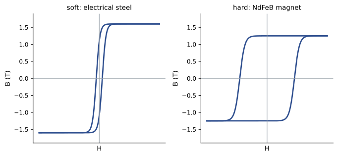
Soft magnetic materials have narrow loops, low losses and are easily magnetized and demagnetized: electrical steels for transformers and motors, ferrites for high-frequency inductors. Hard magnetic materials have wide loops: once magnetized they keep a large remanent field and resist demagnetization, making permanent magnets. Neodymium-iron-boron (NdFeB) magnets, with remanent fields above 1.2 T, have transformed motor design, making possible the compact, efficient permanent-magnet motors of electric vehicles and the direct-drive generators of many large wind turbines; their dependence on rare-earth elements is an important supply-chain concern. All ferromagnets lose their magnetism above a critical temperature (the Curie temperature), and NdFeB magnets begin to weaken at much lower temperatures, so motor cooling matters.
Common mistakes
MistakeExpecting inductor current to change instantly.
InsteadInductor current is continuous; it changes with time constant L/R.
MistakeSwitching an inductive load off without protection.
InsteadFit a flyback diode or snubber to limit the voltage spike.
MistakeForgetting that inductance grows with N².
InsteadDoubling the turns quadruples the inductance.
MistakeUsing solid iron cores for alternating fields.
InsteadLaminate or use ferrite to limit eddy-current loss.
MistakeDesigning a magnetic core into saturation.
InsteadKeep the flux density below the saturation level of the material.
Summary and key terms
- Self-inductance L = NΦ/I; induced emf −L dI/dt opposes changes in current.
- A solenoid has L = μ₀N²A/ℓ, multiplied by μᵣ with a magnetic core.
- An inductor stores ½LI²; field energy density is B²/(2μ₀).
- RL circuits rise and decay with τ = L/R.
- Interrupting inductor current produces large voltage spikes; flyback diodes protect switches.
- Mutual inductance links coils in transformers and wireless chargers; eddy currents heat, brake and detect, and are reduced by laminations.
- Ferromagnets saturate and show hysteresis; soft materials suit cores, hard materials make permanent magnets.
- Self-inductance
- Flux linkage per unit current, L = NΦ/I.
- Henry
- The unit of inductance, one volt-second per ampere.
- Inductive time constant
- τ = L/R, the characteristic time of an RL circuit.
- Flyback diode
- A diode across an inductive load that gives its current a safe path when switched off.
- Mutual inductance
- The emf induced in one coil per unit rate of change of current in another.
- Eddy currents
- Circulating currents induced in a conductor by a changing magnetic field.
- Lamination
- Thin insulated sheets used to build cores that limit eddy currents.
- Relative permeability
- The factor by which a material multiplies the magnetic field compared with vacuum.
- Saturation
- The state in which a magnetic material can add little more flux density.
- Hysteresis
- The dependence of magnetization on past history, causing energy loss per cycle.
Practice problems
Work each problem on paper first, then reveal the answer to check.
A coil has 200 turns and 2 × 10⁻⁵ Wb through each turn at 4 A. Find L.
Show answer
200 × 2 × 10⁻⁵/4 = 1.0 mH.
If the turns of a solenoid are doubled at the same length, how does L change?
Show answer
It quadruples.
Find the emf of a 50 mH inductor when the current falls at 200 A/s.
Show answer
10 V, in the direction that opposes the fall.
How much energy does a 2 H inductor carrying 3 A store?
Show answer
9 J.
Find the energy density in a 1.5 T field.
Show answer
2.25/(2 × 1.257 × 10⁻⁶) = 8.95 × 10⁵ J/m³.
An RL circuit has L = 0.5 H and R = 25 Ω. Find τ.
Show answer
20 ms.
In that circuit with 10 V applied, what is the current after 20 ms?
Show answer
0.4 × 0.632 = 0.25 A.
Why does halving lamination thickness reduce eddy-current loss?
Show answer
Loss scales roughly with the square of thickness, so it falls to about a quarter.
What happens to an iron-core inductor's inductance when the core saturates?
Show answer
It falls sharply, since extra current adds little flux.
Why are permanent-magnet motors popular in electric vehicles?
Show answer
They are compact and efficient, since the rotor field needs no excitation current.
Lesson quiz · 5 questions
Score 60% or more to complete this lesson.
Create a free account to save your progress, take quizzes and earn a certificate.