
ROB-100 · Lesson 12 of 12 · 28 min
Building your first robot project
The best way to understand robots is to build one. Even a small wheeled robot that follows a line or avoids obstacles brings together everything this course has covered: a mechanical structure, actuators and a drive train, sensors, a microcontroller, power, software, feedback control and safety. It also teaches lessons no textbook can, such as how often wires come loose, how differently two supposedly identical motors behave, and how satisfying it is when a machine you built does what you intended. This final lesson guides you through planning and building a first robot: defining the goal and requirements, choosing between kits and your own design, selecting parts and budgeting power, wiring safely, structuring the software, tuning a simple line-following controller, testing systematically and documenting your work. It ends with a capstone project brief that pulls the course together. If you cannot build physical hardware right now, every step can be followed with a free robot simulator instead.
Start with a clear goal
Successful first projects are small and specific. Good examples include a differential-drive robot that follows a black line on a white floor, a robot that wanders a room and turns away from obstacles, a robot that drives to a light or finds its way out of a simple maze, or a small arm that sorts colored blocks using a camera. Write the goal as one sentence, then turn it into a few measurable requirements. For an obstacle-avoiding robot, requirements might be: drive at up to 0.3 m/s on a smooth floor; detect obstacles at least 0.3 m ahead and stop or turn before touching them; run for at least 30 minutes on one charge; fit within a 20 cm square; and cost no more than a set budget. Requirements like these let you choose parts sensibly and know when you have succeeded. Resist the temptation to add features before the basic robot works; extra sensors and arms can come in version two.
Kit or your own design?
A kit includes a chassis, motors, wheels, a microcontroller board, sensors and instructions, so you can concentrate on wiring and programming and be confident the parts work together. Many educational kits are available, from simple two-wheeled chassis to robots designed for ROS 2. Designing your own robot teaches more about mechanical design and part selection but takes longer and involves more troubleshooting. A common middle path is to start with a kit chassis and motors and add your own choice of sensors and software. Popular microcontroller boards for first robots include Arduino-compatible boards, programmed in a C++-based language, and boards such as the Raspberry Pi Pico, which can be programmed in MicroPython. A single-board computer such as a Raspberry Pi running Linux can be added later for cameras and ROS 2.
| Part | Typical choice for a first robot | What to check |
|---|---|---|
| Chassis | Two-wheel acrylic or aluminum kit chassis with caster | Space for battery and boards |
| Motors | Two small DC gear motors with encoders | Voltage, speed, stall current |
| Motor driver | Dual H-bridge driver board | Current rating above motor stall current |
| Controller | Arduino-compatible board or Raspberry Pi Pico | Enough PWM, analog and digital pins |
| Sensors | Ultrasonic range sensor, line sensors, bump switch | Range, voltage level, update rate |
| Power | NiMH or protected lithium-ion pack, switch, fuse | Voltage, capacity, safe charging |
| Wiring | Jumper wires, terminal blocks, connectors | Secure connections, strain relief |
Power budget and runtime
Before buying a battery, estimate how much power the robot needs, just as in lesson 3. List each part with its typical current at the battery voltage, multiply by the time it is drawing that current, and add a margin. Motors dominate: check the motor's running current under load and its stall current, the current it draws when blocked, which can be several times higher and determines the motor driver's rating and the fuse size. Remember that voltage regulators, which supply the microcontroller and sensors with a steady lower voltage, waste some energy, and that batteries deliver less than their rated capacity when cold, old or drained quickly.
Worked problem
A power budget for a first robot
A robot runs from a 7.4 V lithium-ion pack rated 2,600 mAh. While driving, its two motors draw 0.35 A each, the microcontroller and sensors draw 0.12 A, and an indicator display draws 0.03 A, all from the pack. The builder plans to use 80 % of the capacity. Estimate the driving runtime. Does it meet a 30-minute requirement?
Show solution
- Total current: \( 2 \times 0.35 + 0.12 + 0.03 = 0.85 \) A.
- Usable capacity: \( 2.6 \times 0.8 = 2.08 \) Ah.
- Runtime: \( 2.08 / 0.85 \approx 2.45 \) h, about 2 h 27 min.
- This easily meets the 30-minute requirement, leaving margin for stalls, climbing and an aging battery.
Answer: About 2.4 hours, comfortably more than 30 minutes.
Wiring and electrical safety
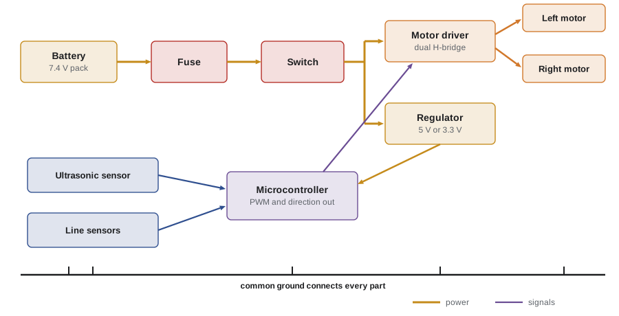
Most first-robot problems are wiring problems. Plan the wiring on paper first, showing which pins connect to what. Keep motor power and logic power organized, connect all grounds together so signals share a common reference, and check that sensor signal voltages match the microcontroller: many boards use 3.3 V logic and can be damaged by 5 V signals. Never power motors directly from a microcontroller pin, which can supply only a few milliamps; use a motor driver, which switches the larger motor current under the microcontroller's control. A pulse-width modulation (PWM) signal from the microcontroller sets the motor's speed by switching it on and off rapidly and varying the fraction of time it is on, called the duty cycle, while direction pins set which way it turns.
Batteries deserve respect. Lithium-ion and especially lithium polymer packs can overheat, swell and catch fire if short-circuited, overcharged, over-discharged or punctured. Use packs with built-in protection or a battery management board, charge them only with a suitable charger in a fire-safe place and never unattended, include a fuse and an easily reached power switch close to the battery, and insulate exposed connections. NiMH packs are a lower-risk choice for beginners. When testing, lift the robot so its wheels spin freely before letting it loose on the floor, keep long hair, loose clothing and fingers away from moving parts, and make sure you can stop it instantly.
Structuring the software
Even a small robot benefits from tidy software. A good structure is a main loop that runs at a steady rate, say 50 times a second, and in each cycle reads the sensors, updates a simple state machine that decides what the robot is doing, computes motor commands with a controller, and sends them to the motor driver. Keep separate functions for reading each sensor, for driving the motors and for each behavior, so you can test each piece on its own. An obstacle-avoiding robot might have states for driving forward, stopping, backing up and turning, with transitions triggered when the ultrasonic sensor reads less than 0.3 m or when a turn has lasted long enough. Print sensor readings and the current state to a serial monitor or log while developing, so you can see what the robot believes. Use version control, even for a small project, so you can return to a version that worked.
Tuning a line follower
A line-following robot is a classic first exercise in feedback control. Two or more reflectance sensors under the front of the robot measure how much light bounces back from the floor; a black line reflects less than a white floor. With two sensors straddling the line, the difference between their readings tells the robot which side the line is on and roughly how far. That difference is the error. A proportional controller then sets the turning rate in proportion to the error, slowing one wheel and speeding up the other: \( v_L = v_0 + K_p e \) and \( v_R = v_0 - K_p e \), where \( v_0 \) is the base speed and the sign convention depends on how the sensors are wired. If the robot wanders off the line, increase the gain; if it zigzags violently, reduce it or lower the base speed; adding a derivative term often smooths the motion, just as lesson 7 described.
Worked problem
Proportional line following
A line follower has two sensors that give readings from 0 (white) to 1,000 (black). The error is left reading minus right reading. The base wheel command is 150 (out of a maximum of 255) and Kp = 0.08, with left command = base + Kp × error and right command = base − Kp × error. The left sensor reads 700 and the right 200. Find the wheel commands. Which way does the robot turn, and is that correct?
Show solution
- Error: \( 700 - 200 = 500 \).
- Correction: \( 0.08 \times 500 = 40 \).
- Left command: \( 150 + 40 = 190 \); right command: \( 150 - 40 = 110 \).
- The left wheel turns faster, so the robot turns right. The left sensor sees more of the black line, so the line is toward the left: with this wiring the robot turns the wrong way, and the sign of Kp, or of the error, must be flipped.
Answer: Left 190 and right 110, turning right; since the line is to the left, the sign convention must be reversed.
Getting a sign backwards, as in the example, is one of the most common mistakes in robotics, and the fix is simple once you notice it. Test each sensor and motor separately first, confirm which direction is positive, and then close the loop.
Testing, debugging and iteration
Build and test in small steps. Check that each motor spins in the right direction at different PWM levels with the wheels off the ground; check that each sensor gives sensible readings as you move objects in front of it; then combine them, one behavior at a time. When something goes wrong, change one thing at a time, keep notes and look at the data rather than guessing. Measure performance against your requirements: time how long the battery lasts, measure the distance at which the robot actually detects obstacles of different materials, and count how often it completes the course. Expect to iterate: most robots go through several versions as builders discover problems with mounting, wiring, sensor placement and tuning. Each version teaches something.
| Symptom | Likely causes | What to try |
|---|---|---|
| Robot spins instead of driving straight | One motor reversed or wired backwards | Swap that motor's wires or invert it in code |
| Robot veers to one side | Motors differ, wheels slip | Use encoder feedback to match wheel speeds |
| Microcontroller resets when motors start | Voltage dips from motor current | Separate supplies, add capacitors, check battery |
| Ultrasonic readings jump randomly | Angled or soft surfaces, crosstalk | Filter readings, aim the sensor, average samples |
| Line follower oscillates | Gain too high or speed too fast | Lower Kp or speed, add derivative term |
Simulation, documentation and next steps
If you do not have hardware, or want to test ideas before building, robot simulators such as Webots and Gazebo, and browser-based simulators for educational robots, let you build and program virtual robots for free, and the same ROS 2 code can later run on real hardware. Whatever you build, document it: photos, a wiring diagram, your code with comments, a short video of the robot working and a page describing your requirements, what you tried, what failed and what you would change. That documentation becomes the first entry in your portfolio, as lesson 11 suggested. From here, natural next steps are adding encoders and closed-loop speed control, mounting a Raspberry Pi and camera, learning ROS 2, joining a robotics team or competition, and continuing with the programming, electronics and kinematics courses in the Robotics program.
Capstone: plan a robot
To bring the course together, plan a robot of your own on paper, whether or not you build it. Choose a task in a setting covered in lesson 9 and write a one-page design brief that covers: the task and why a robot suits it; the robot's level of autonomy and its operational design domain; its form and locomotion, with its degrees of freedom; its sensors, with the range and resolution they need; its actuators and drive train, with a rough gear-ratio or thrust check; its power system, with a runtime estimate; its software architecture, with a simple state machine; its main control loop; its hazards and the safety measures you would apply, following the hierarchy of controls and the relevant standards in your country; the ethical questions it raises; and, if it is a commercial robot, a rough payback estimate. Comparing your brief with a classmate's, or with a real robot that does a similar job, is an excellent way to see how far you have come.
Common mistakes
MistakeStarting with an ambitious multi-sensor robot.
InsteadBegin with a small, specific goal and add features once it works.
MistakePowering motors from a microcontroller pin.
InsteadUse a motor driver rated above the motors' stall current.
MistakeCharging lithium batteries unattended or without protection.
InsteadUse protected packs, proper chargers, fuses and a fire-safe place.
MistakeTesting everything at once on the floor.
InsteadTest each part separately, wheels off the ground, before combining.
MistakeChanging several things at once when debugging.
InsteadChange one thing at a time and record what happens.
Summary and key terms
- A first robot should have a clear, small goal and measurable requirements.
- Kits reduce risk; your own designs teach more; mixing the two works well.
- A power budget sizes the battery, motor driver and fuse.
- Wire carefully with a common ground, correct logic levels, a motor driver and battery protection.
- Structure software as a steady main loop with sensors, a state machine and controllers.
- A line follower uses proportional control; check signs and tune the gain.
- Test in small steps, document everything and plan the next version.
- Requirement
- A measurable statement of what a robot must do.
- Microcontroller board
- A small computer board that reads sensors and drives outputs.
- Motor driver
- A circuit that switches motor current under logic control.
- H-bridge
- A motor driver circuit that can drive a motor in both directions.
- PWM
- Pulse-width modulation, switching power on and off to vary its average.
- Duty cycle
- The fraction of time a PWM signal is on.
- Stall current
- The current a motor draws when prevented from turning.
- Common ground
- A shared reference connection for all circuits.
- Reflectance sensor
- A sensor that measures light reflected from a surface.
- Design brief
- A short document describing a system's purpose and design.
Practice problems
Work each problem on paper first, then reveal the answer to check.
Write one measurable requirement for an obstacle-avoiding robot.
Show answer
For example: stop or turn before reaching 0.3 m from an obstacle.
Why use a motor driver?
Show answer
Microcontroller pins cannot supply motor current.
What does PWM duty cycle control?
Show answer
The average power, and so the speed, of a motor.
Total current of two 0.4 A motors and 0.2 A of electronics?
Show answer
1.0 A.
Runtime of 1.6 Ah usable at 0.8 A?
Show answer
2 hours.
Why connect grounds together?
Show answer
So signals share a common reference.
Error 300, Kp 0.1, base 120. Left and right commands?
Show answer
150 and 90.
Line follower zigzags violently. What do you try?
Show answer
Lower Kp or speed, or add a derivative term.
Microcontroller resets when motors start. Likely cause?
Show answer
Voltage dips from motor current.
Name two things to include in project documentation.
Show answer
Photos, wiring diagram, code, video, write-up of lessons.
Lesson quiz · 5 questions
Score 60% or more to complete this lesson.
Create a free account to save your progress, take quizzes and earn a certificate.