
ROB-200 · Lesson 11 of 12 · 26 min
Motor drivers and power electronics
A microcontroller pin can supply a few milliamperes at 3.3 V; a robot's drive motors may need 20 A at 24 V, in either direction, with smoothly varying speed, regenerative braking and protection against stalls and short circuits. The motor driver bridges that gap. This lesson brings together everything so far: the MOSFET switches of lesson 3, the PWM and dead time of lesson 7, and the current sensing of lesson 8. You will learn how brushed DC motors behave electrically, how an H-bridge drives them in both directions, the difference between coasting and braking, how to size a driver for current and heat, what happens to the energy when a motor slows down, and how brushless motors are driven by three half-bridges.
The brushed DC motor as a circuit
Electrically, a brushed DC motor is a winding with resistance R and inductance L, in series with a voltage source called the back-EMF. As the motor spins, it acts as a generator, producing a voltage proportional to its speed, E = Ke ω, which opposes the applied voltage. The current, and therefore the torque, depends on the difference between the applied voltage and the back-EMF. Torque is proportional to current, τ = Kt I, and in SI units the torque constant Kt (N·m/A) equals the back-EMF constant Ke (V·s/rad).
These equations explain the behavior that surprises beginners. At standstill there is no back-EMF, so the current is limited only by the winding resistance: the stall current, often five to twenty times the running current. Every start is briefly a stall, as is every collision that stops a wheel. A motor running freely with no load draws little current because its back-EMF nearly equals the supply. Under load it slows, back-EMF falls, and current and torque rise to match the load. The driver, wiring, fuses and battery must survive the stall current, or the driver must limit current.
import math
V, R, K = 24.0, 0.8, 0.045      # supply (V), winding (ohm), Kt = Ke (SI units)
I_stall = V / R
w_free = V / K                   # ideal no-load speed (rad/s), ignoring friction
print(f"stall current = {I_stall:.0f} A, stall torque = {K*I_stall:.2f} N m")
print(f"no-load speed = {w_free*60/(2*math.pi):.0f} rpm")
for load_nm in (0.1, 0.3, 0.6):
    I = load_nm / K
    w = (V - I * R) / K
    p_in, p_out = V * I, load_nm * w
    print(f"load {load_nm:.1f} N m: I = {I:5.1f} A, "
f"{w*60/(2*math.pi):5.0f} rpm, efficiency {p_out/p_in*100:4.1f} %")stall current = 30 A, stall torque = 1.35 N m no-load speed = 5093 rpm load 0.1 N m: I = 2.2 A, 4716 rpm, efficiency 92.6 % load 0.3 N m: I = 6.7 A, 3961 rpm, efficiency 77.8 % load 0.6 N m: I = 13.3 A, 2829 rpm, efficiency 55.6 %
The motor's electrical time constant, L/R, is typically a fraction of a millisecond to a few milliseconds. If the PWM period is much shorter, the winding inductance smooths the current into a nearly steady value with a small ripple; this is why the 16 to 25 kHz PWM frequencies of lesson 7 work well. Mechanical time constants, how quickly the motor and its load change speed, are much longer, tens to hundreds of milliseconds.
The H-bridge
To reverse a DC motor, the voltage across it must reverse. An H-bridge does this with four switches arranged like the letter H, the motor forming the crossbar. Closing the top-left and bottom-right switches drives current one way; closing top-right and bottom-left drives it the other. Each side of the H is a half-bridge, a high-side and a low-side MOSFET between the supply and ground with the motor connected at their midpoint. The forbidden combination is closing both switches on the same side, which shorts the supply through them, called shoot-through, and destroys the MOSFETs within microseconds. Dead time, the short gap when both are off that lesson 7 described, prevents it during switching.
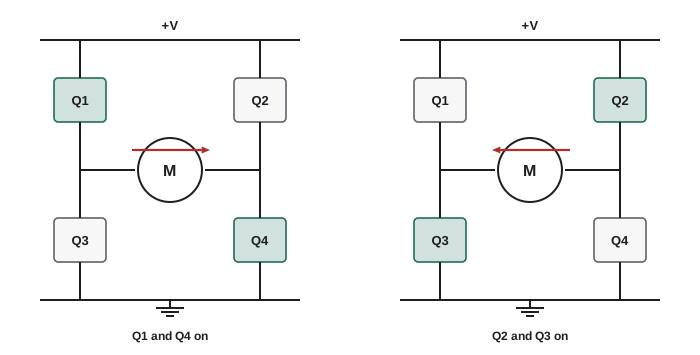
With PWM, the bridge alternates between driving and a second state during the off-time. In sign-magnitude drive with fast decay, all switches turn off and the motor current flows back through the MOSFETs' body diodes to the supply, decaying quickly. With slow decay, both low-side switches close, shorting the motor so the current circulates and decays slowly. Slow decay gives a more linear relationship between duty cycle and speed and lower current ripple, so it is common for robot drive motors. Locked anti-phase drive, the alternative, switches the diagonals in turn and sets direction by whether the duty cycle is above or below 50 %.
| Bridge state | Switches on | Effect on the motor |
|---|---|---|
| Forward drive | High-left, low-right | Supply applied forward; accelerates or holds speed |
| Reverse drive | High-right, low-left | Supply applied in reverse |
| Coast (fast decay) | None | Current decays through body diodes; motor freewheels |
| Brake (slow decay) | Both low-side | Motor terminals shorted; back-EMF drives a braking current |
| Shoot-through (forbidden) | High and low on the same side | Supply shorted; MOSFETs destroyed |
Braking by shorting the motor terminals deserves a closer look. The spinning motor's back-EMF drives current through its own resistance, producing torque that opposes the motion and turning kinetic energy into heat in the winding. This dynamic braking stops a robot faster than coasting, and some drivers use it as their default stop. But it is not a holding brake: once the motor stops, so does the braking torque, and a robot on a slope will roll. Robots that must hold position without power, such as arms and robots on ramps, use spring-applied electromechanical brakes that release only when energized.
Regeneration: where the energy goes
When a robot decelerates or drives down a slope while the bridge is applying a voltage lower than the back-EMF, the motor acts as a generator and current flows back into the supply. With a battery, that regenerated energy recharges it, within the battery's charge-current limit. With a bench power supply, which cannot absorb current, or a battery whose BMS has disconnected because it is full, the energy has nowhere to go and the supply voltage rises, sometimes enough to destroy the driver and everything else on the rail. Robots therefore need a path for regenerated energy: the battery itself, large bulk capacitors for brief events, or a braking chopper that switches the excess into a power resistor when the bus voltage rises above a threshold.
Worked problem
How much does the bus voltage rise?
A 30 kg robot moving at 1.5 m/s brakes regeneratively. The battery has been disconnected, so the only storage on the 24 V bus is 2,000 µF of capacitance. If all the kinetic energy went into the capacitors, how high would the voltage rise?
Show solution
- Kinetic energy: \( \tfrac12 m v^2 = 0.5 \times 30 \times 1.5^2 = 33.8 \) J.
- Capacitor energy: \( \tfrac12 C V^2 \). At 24 V it holds \( 0.5 \times 0.002 \times 24^2 = 0.58 \) J.
- Final energy \( 0.58 + 33.8 = 34.3 \) J, so \( V = \sqrt{2 \times 34.3 / 0.002} \approx 185 \) V.
- Losses would absorb some of this, but the bus would still far exceed any 40 or 60 V rating.
Answer: In principle well over 100 V, enough to destroy the electronics. The battery must stay connected while braking, or a braking chopper must dump the energy.
Sizing a driver: current and heat
A driver's continuous current rating depends heavily on cooling, so treat headline numbers with caution. Losses in an H-bridge come from two sources. Conduction losses are I²RDS(on) in each conducting MOSFET; two are on at a time in forward or reverse drive. Switching losses occur during each transition, roughly proportional to the supply voltage, the current, the switching time and the PWM frequency. Datasheets for integrated drivers often give total on-resistance for the high-side plus low-side path. Adding the losses and multiplying by the thermal resistance gives the temperature rise, as in lesson 3.
def bridge_losses(v, i, rds_hot, t_sw, f_pwm):
    p_cond = i**2 * 2 * rds_hot            # two MOSFETs conduct
    p_sw = 0.5 * v * i * (2 * t_sw) * f_pwm * 2   # one switching leg, 2 devices
    return p_cond, p_sw

for i in (5, 10, 20):
    for f in (20_000, 50_000):
        pc, ps = bridge_losses(24, i, 0.008, 50e-9, f)
        print(f"I = {i:2d} A, {f//1000:2d} kHz: conduction {pc:5.2f} W, "
f"switching {ps:5.2f} W, total {pc+ps:5.2f} W")I = 5 A, 20 kHz: conduction 0.40 W, switching 0.24 W, total 0.64 W I = 5 A, 50 kHz: conduction 0.40 W, switching 0.60 W, total 1.00 W I = 10 A, 20 kHz: conduction 1.60 W, switching 0.48 W, total 2.08 W I = 10 A, 50 kHz: conduction 1.60 W, switching 1.20 W, total 2.80 W I = 20 A, 20 kHz: conduction 6.40 W, switching 0.96 W, total 7.36 W I = 20 A, 50 kHz: conduction 6.40 W, switching 2.40 W, total 8.80 W
Conduction losses grow with the square of current and dominate at high current; switching losses grow with frequency. That is the engineering trade-off behind choosing a PWM frequency. In addition, the driver must handle the peak current at stall or collision, and the real solution is current limiting: the driver measures current, through shunts and amplifiers as in lesson 8 or through the MOSFETs' own on-resistance, and reduces the duty cycle or shuts down when it exceeds a limit. Many integrated drivers provide cycle-by-cycle current limiting, thermal shutdown, undervoltage lockout and a fault output pin, which should go to a microcontroller interrupt as in lesson 6.
Integrated drivers and gate drivers
For small motors, single-chip H-bridge drivers integrate the four MOSFETs, gate drive, current sensing and protection, and accept simple PWM and direction inputs; they handle from a few hundred milliamperes to roughly 5 to 10 A. Older bipolar-transistor drivers such as the L298 family, still common in kits, drop two volts or more across their transistors and waste a great deal of power; modern MOSFET drivers are far better. For larger motors, a gate-driver chip drives discrete MOSFETs: it level-shifts the logic signals, provides the 10 to 12 V gate voltage, generates the high-side gate voltage with a bootstrap capacitor, inserts dead time and protects against shoot-through and undervoltage. The PWM timer's complementary outputs and break input, from lesson 7, connect straight to it.
/* Drive one H-bridge with an advanced timer: complementary PWM with dead time.
   Duty in the range -1.0 .. +1.0. Sign sets direction (sign-magnitude drive). */
void bridge_set(float duty) {
    if (duty >  0.95f) duty =  0.95f;          /* leave headroom for bootstrap */
    if (duty < -0.95f) duty = -0.95f;
    uint32_t ccr = (uint32_t)(fabsf(duty) * (TIM1->ARR + 1));
    if (duty >= 0.0f) {
        TIM1->CCR1 = ccr;   /* left leg switches with PWM          */
        TIM1->CCR2 = 0;     /* right leg: low side held on          */
    } else {
        TIM1->CCR1 = 0;
        TIM1->CCR2 = ccr;
    }
}
/* Dead time and the break input (driver fault, e-stop) are configured once
   at start-up in the timer's BDTR register, so protection works even if
   this code hangs. */
Brushless motors
Brushless DC motors (BLDC), now standard in drones, many robot joints and mobile bases, put the windings on the stationary part and the magnets on the rotor, removing the brushes that wear and spark. They are driven by three half-bridges, one per phase, which switch the phases in sequence according to the rotor position measured by Hall sensors, an encoder, or estimated from back-EMF. Simple six-step (trapezoidal) commutation energizes two phases at a time. Field-oriented control (FOC) measures the phase currents and continuously computes sinusoidal voltages that keep the magnetic field at the optimal angle to the rotor, giving smooth, quiet, efficient torque control; it is how most robot joint actuators are driven. The mathematics of FOC and the current, velocity and position loops wrapped around it belong to ROB-300 and ROB-220; the hardware is the same half-bridges, gate drivers, current sensing and timers you have now met.
Common mistakes
MistakeSizing the driver for the motor's running current only.
InsteadAllow for stall current at every start and collision, or use a driver with current limiting.
MistakeTurning on both MOSFETs of a half-bridge, even briefly.
InsteadUse hardware dead time and drivers with shoot-through protection.
MistakeTesting a regenerating motor drive on a bench supply without protection.
InsteadUse a battery, a supply that can sink current, or a braking resistor and clamp.
MistakeRelying on dynamic braking to hold a robot on a slope.
InsteadUse a spring-applied brake; braking torque vanishes at zero speed.
MistakeChoosing an old bipolar H-bridge for a battery robot.
InsteadUse a MOSFET driver; bipolar drivers waste volts and watts as heat.
Summary and key terms
- A brushed DC motor is resistance and inductance in series with a back-EMF proportional to speed.
- Torque is proportional to current; at stall, current is V/R, often many times the running current.
- An H-bridge reverses voltage with diagonal switch pairs; same-side conduction (shoot-through) must never happen.
- Fast decay coasts through body diodes; slow decay shorts the motor for braking and smoother control.
- Regenerated energy must go into the battery, capacitors or a braking resistor, or the bus voltage soars.
- Driver losses are I²RDS(on) conduction plus switching losses proportional to PWM frequency; limit current.
- Brushless motors use three half-bridges with commutation or field-oriented control.
- Back-EMF
- The voltage a spinning motor generates, proportional to speed, opposing the supply.
- Torque constant
- The torque produced per ampere of motor current.
- Stall current
- The current a motor draws when held stationary at full voltage, V/R.
- H-bridge
- Four switches that apply a voltage to a motor in either direction.
- Half-bridge
- A high-side and a low-side switch with the load at their midpoint.
- Shoot-through
- Both switches of a half-bridge conducting at once, shorting the supply.
- Slow decay
- Recirculating motor current through both low-side switches, braking the motor.
- Regenerative braking
- Returning a motor's kinetic energy to the supply as it slows.
- Gate driver
- A chip that drives MOSFET gates with suitable voltages, dead time and protection.
- Field-oriented control
- Controlling a brushless motor by regulating phase currents relative to rotor position.
Practice problems
Work each problem on paper first, then reveal the answer to check.
A 12 V motor has 1.5 Ω winding resistance. What is its stall current?
Show answer
8 A.
A motor with Kt = 0.05 N·m/A carries 6 A. What torque does it produce?
Show answer
0.3 N·m.
With Ke = 0.05 V·s/rad at 200 rad/s, what is the back-EMF?
Show answer
10 V.
Which H-bridge switches drive current left to right through the motor?
Show answer
High-side left and low-side right.
Why does slow decay brake the motor?
Show answer
The shorted terminals let back-EMF drive a current that produces opposing torque.
A bridge with 10 mΩ hot MOSFETs carries 15 A. What is the conduction loss?
Show answer
15² × 0.02 = 4.5 W.
What happens to the bus voltage when a motor regenerates into a supply that cannot absorb current?
Show answer
It rises, possibly to destructive levels.
What does a bootstrap capacitor do in a gate driver?
Show answer
Provides a gate voltage above the supply for the high-side N-channel MOSFET.
Why do many drivers limit PWM duty to about 95 to 98 %?
Show answer
The bootstrap capacitor needs the low side to switch on periodically to recharge.
How many half-bridges drive a three-phase brushless motor?
Show answer
Three.
Lesson quiz · 5 questions
Score 60% or more to complete this lesson.
Create a free account to save your progress, take quizzes and earn a certificate.