
ROB-200 · Lesson 9 of 12 · 30 min
Serial buses: UART, I2C and SPI
A microcontroller on a robot is surrounded by chips and modules it must talk to: an inertial measurement unit, a magnetometer, a barometer, a time-of-flight distance sensor, an external ADC, a GPS receiver, a display, smart servos and the Linux computer upstairs. Sending data one bit at a time over a few wires, serial communication, keeps the wiring manageable. Three serial interfaces handle most of this traffic on and near the circuit board: UART for point-to-point links, I2C for many slow devices on two shared wires, and SPI for fast data from a few devices. This lesson explains how each works at the level of signals, how to calculate their timing and bandwidth, how to choose between them and how to debug them when they fail.
UART: asynchronous serial
A UART (universal asynchronous receiver-transmitter) sends bytes over one wire in each direction, TX to the other device's RX, with a common ground. There is no clock wire; both ends agree in advance on the baud rate, the number of bit periods per second, commonly 9,600, 115,200, or 1 Mbaud and above. Each frame starts with a start bit (low), carries 8 data bits least significant first, optionally a parity bit, and ends with one or more stop bits (high). The common 8N1 format, 8 data bits, no parity, 1 stop bit, takes 10 bit periods per byte, so 115,200 baud carries at most 11,520 bytes per second.
Because there is no clock, the receiver times each bit from the falling edge of the start bit, sampling near the middle of each bit period. If the two ends' bit rates differ, the sampling point drifts by the end of the frame. A total mismatch of more than about 2 to 3 % between the two ends risks errors, so each end should be within about ±2 %, less at high baud rates. Baud error comes from dividing the peripheral clock by an integer: not every baud rate divides evenly, and an internal RC oscillator adds its own error, which is why robot boards use crystals for serial and CAN.
def baud_error(f_clk, baud, oversample=16):
    div = round(f_clk / (oversample * baud))
    actual = f_clk / (oversample * div)
    return div, actual, (actual - baud) / baud * 100

for f_clk in (16_000_000, 48_000_000):
    for baud in (9_600, 115_200, 1_000_000):
        div, actual, err = baud_error(f_clk, baud)
        flag = "OK" if abs(err) < 2 else "TOO HIGH"
        print(f"{f_clk/1e6:4.0f} MHz {baud:8d} baud: div {div:4d} "
f"actual {actual:10.0f} error {err:+6.2f} % {flag}")16 MHz 9600 baud: div 104 actual 9615 error +0.16 % OK 16 MHz 115200 baud: div 9 actual 111111 error -3.55 % TOO HIGH 16 MHz 1000000 baud: div 1 actual 1000000 error +0.00 % OK 48 MHz 9600 baud: div 312 actual 9615 error +0.16 % OK 48 MHz 115200 baud: div 26 actual 115385 error +0.16 % OK 48 MHz 1000000 baud: div 3 actual 1000000 error +0.00 % OK
The classic 16 MHz Arduino cannot make 115,200 baud accurately with a whole-number divider, about 3.5 % off, which is why such boards often use a double-speed mode with 8× oversampling (+2.1 %) or prefer rates such as 250,000 or 1,000,000 that divide evenly. Many modern microcontrollers have fractional baud-rate generators that reduce the error to a fraction of a percent. UART signals at microcontroller logic levels are fine for short links on a board or within a robot; for longer or noisier runs, transceivers convert them to RS-232 (higher voltage, single-ended) or RS-485 (differential, multi-drop, hundreds of meters), and USB-to-UART bridges connect a microcontroller to a computer, appearing in Linux as /dev/ttyUSB0 or /dev/ttyACM0, as you met in ROB-110.
Worked problem
Will the link keep up?
A microcontroller sends the Linux computer an odometry packet of 32 bytes plus 6 bytes of framing and checksum, 100 times per second, over 8N1 UART. Is 115,200 baud enough? What about 921,600?
Show solution
- Bits per second needed: \( 38 \times 10 \times 100 = 38\,000 \).
- At 115,200 baud the link is \( 38\,000/115\,200 \approx 33\% \) busy, acceptable but leaving limited room for more data.
- Each packet takes \( 380 / 115\,200 \approx 3.3 \) ms to send, which adds latency.
- At 921,600 baud the link is about 4 % busy and each packet takes about 0.41 ms.
Answer: 115,200 baud works at about one-third load; 921,600 baud gives headroom and lower latency, if both ends can generate it accurately.
Because UART only moves bytes, robot links also need a protocol: a way to mark where packets start, say what they contain and detect corruption. Common choices are a start byte with a length and a CRC, or byte-stuffing schemes such as COBS that guarantee a unique delimiter. Micro-ROS, covered in lesson 10, and MAVLink, used in drones, are complete protocols that run over UART among other links.
I2C: two wires, many devices
I2C (inter-integrated circuit) connects many devices using just two shared lines: SDA for data and SCL for the clock, plus ground. One device, usually the microcontroller, is the controller that generates the clock; the others are targets, each with a 7-bit address, usually fixed by the manufacturer with one or two pins to change it. Both lines are open-drain, so any device can pull them low, and pull-up resistors pull them high, which is what lets many devices share them safely. Standard speeds are 100 kHz (standard mode), 400 kHz (fast mode) and 1 MHz (fast-mode plus).
A transaction begins with a start condition, SDA falling while SCL is high, followed by the target's address and a read/write bit. The addressed target acknowledges by pulling SDA low for one clock (ACK). Data then follow in bytes, each acknowledged, and a stop condition, SDA rising while SCL is high, ends the transaction. To read a sensor register, the controller typically writes the register address, then issues a repeated start and reads one or more bytes. Most sensors auto-increment the register address, so a single transaction can read all six bytes of a three-axis accelerometer at once, which keeps the values from different axes consistent with each other.
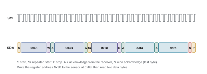
from machine import I2C, Pin
import time

i2c = I2C(0, scl=Pin(5), sda=Pin(4), freq=400_000)
print([hex(a) for a in i2c.scan()])      # e.g. ['0x68']

ADDR, PWR, ACCEL = 0x68, 0x6B, 0x3B       # from the sensor datasheet
i2c.writeto_mem(ADDR, PWR, b'\x00')        # wake the sensor
time.sleep_ms(10)

def s16(hi, lo):
    v = (hi << 8) | lo
    return v - 65536 if v & 0x8000 else v

d = i2c.readfrom_mem(ADDR, ACCEL, 6)      # X, Y, Z high/low bytes
ax, ay, az = s16(d[0], d[1]), s16(d[2], d[3]), s16(d[4], d[5])
print(ax / 16384, ay / 16384, az / 16384)  # in g at +/-2 g range
The pull-up resistors limit I2C speed. The bus capacitance, from every device's pins and the wiring, must charge through them, so the rise time is about 0.85 RC for the 30 % to 70 % thresholds the specification uses, and the specification caps it at 1,000 ns in standard mode and 300 ns in fast mode. Pull-ups too large give slow edges; too small and the devices cannot sink enough current to pull the line low, 3 mA being the guaranteed figure in standard and fast modes. Total bus capacitance is limited to 400 pF.
Worked problem
Choosing I2C pull-ups
A 3.3 V fast-mode (400 kHz) bus has four sensors and short wiring, with about 120 pF total. VOL(max) is 0.4 V at 3 mA. What range of pull-up values works?
Show solution
- \( R_{\min} = (3.3 - 0.4)/0.003 \approx 967\ \Omega \).
- \( R_{\max} = 300 \times 10^{-9} / (0.8473 \times 120 \times 10^{-12}) \approx 2.95\ \text{k}\Omega \).
- Choose 2.2 kΩ, comfortably inside the range. Many breakout boards each add their own 10 kΩ pull-ups; four in parallel make 2.5 kΩ, so check the combined value.
Answer: Between about 1 kΩ and 2.9 kΩ; 2.2 kΩ is a good choice.
def i2c_pullup_range(vdd, c_bus, t_r, vol=0.4, iol=0.003):
    return (vdd - vol) / iol, t_r / (0.8473 * c_bus)

for mode, tr in (("standard 100 kHz", 1000e-9), ("fast 400 kHz", 300e-9)):
    for c in (50e-12, 120e-12, 300e-12):
        lo, hi = i2c_pullup_range(3.3, c, tr)
        ok = "OK" if hi > lo else "impossible: reduce capacitance"
print(f"{mode:17s} C = {c*1e12:3.0f} pF: {lo:5.0f} to {hi:6.0f} ohm {ok}")standard 100 kHz C = 50 pF: 967 to 23604 ohm OK standard 100 kHz C = 120 pF: 967 to 9835 ohm OK standard 100 kHz C = 300 pF: 967 to 3934 ohm OK fast 400 kHz C = 50 pF: 967 to 7081 ohm OK fast 400 kHz C = 120 pF: 967 to 2951 ohm OK fast 400 kHz C = 300 pF: 967 to 1180 ohm OK
I2C was designed for connections on one circuit board, not long cables. Off-board runs of more than about half a meter beside motors invite errors, and a target stuck holding SDA low after a glitch can hang the whole bus; firmware should detect this and clock SCL up to nine times to release it. For longer runs, use a bus extender or differential I2C chips, or choose CAN. Two devices with the same address cannot share a bus without an address-select pin or an I2C multiplexer, a common problem when a robot uses several identical distance sensors.
SPI: fast and simple
SPI (serial peripheral interface) uses four wires: a clock (SCK) generated by the controller, data from controller to device (often labeled MOSI, or COPI and SDO in newer naming), data from device to controller (MISO, CIPO or SDI), and a chip-select line (CS) for each device, active low. Data move in both directions at once, one bit per clock, and there is no addressing or acknowledgment: the controller simply pulls a device's CS low and clocks bytes in and out. SPI's push-pull lines allow clock rates of 10 to 50 MHz or more, making it the choice for high-rate IMUs, fast ADCs, displays, flash memory and some encoders.
SPI has four modes, set by clock polarity (CPOL, whether the clock idles low or high) and clock phase (CPHA, whether data are sampled on the first or second edge). Controller and device must use the same mode; mode 0 and mode 3 are most common. Getting the mode wrong gives data shifted by one bit or garbage, a classic first-day problem. The cost of SPI is pins: each device needs its own chip select, so three devices use six wires, not two. Like I2C, SPI is meant for short connections.
| UART | I2C | SPI | |
|---|---|---|---|
| Wires (plus ground) | 2 (TX, RX) | 2 shared (SDA, SCL) | 3 shared + 1 CS per device |
| Clock | None; agreed baud rate | Controller drives SCL | Controller drives SCK |
| Devices | Point to point | Up to about 100+ by address | One per chip-select line |
| Typical speed | 115 kbaud to a few Mbaud | 100 kHz, 400 kHz, 1 MHz | 1 to 50+ MHz |
| Acknowledgment | No (protocol may add) | Yes, every byte | No |
| Robot uses | Link to Linux computer, GPS, smart servos | Slow sensors, displays, EEPROM, BMS | Fast IMUs, ADCs, flash, displays |
Worked problem
SPI bandwidth for an IMU
An IMU outputs 12 bytes of data (accelerometer and gyroscope) at 8 kHz. Each read sends one command byte first. At an SPI clock of 10 MHz, what fraction of the bus does this use?
Show solution
- Bytes per read: 13, or 104 bits, taking \( 104 / 10\,000\,000 = 10.4\ \mu\text{s} \).
- Reads per second: 8,000, so busy time is \( 8000 \times 10.4\ \mu\text{s} = 83 \) ms per second, 8.3 %.
- In practice, gaps between bytes and chip-select set-up time add overhead; DMA transfers reduce the processor's involvement to nearly zero.
Answer: About 8 % of the bus at 10 MHz. The same data over 400 kHz I2C would need about 260 % of the bus, which is impossible.
Debugging serial links
Serial bugs are easier to find with a logic analyzer, a tool that records digital signals on several channels and decodes UART, I2C and SPI into bytes on a computer screen. Inexpensive USB analyzers are among the best investments for a robotics team. Typical findings include swapped TX and RX lines, missing ground connections, wrong baud rates, missing or doubled pull-ups, I2C targets that never acknowledge because the address is wrong (datasheets sometimes give the 8-bit form including the read/write bit, such as 0xD0 instead of 0x68), SPI mode mismatches and chip-select lines that never go low. An oscilloscope then shows whether edges are clean or slow, ringing or noisy, which the next lessons build on.
Common mistakes
MistakeConnecting TX to TX and RX to RX.
InsteadCross them: each device's TX goes to the other's RX, with a shared ground.
MistakeAssuming any baud rate works with any clock.
InsteadCalculate the baud error and keep each end within about ±2 %; use crystals.
MistakeRunning I2C over long cables beside motors.
InsteadKeep I2C on the board or short harnesses; use extenders or CAN for longer runs.
MistakeForgetting that every breakout board adds its own I2C pull-ups.
InsteadCalculate the combined parallel value and remove extras if it falls below the minimum.
MistakeUsing an 8-bit I2C address from a datasheet with a library expecting 7 bits.
InsteadShift right by one: 0xD0 becomes 0x68.
Summary and key terms
- UART sends framed bytes without a clock; both ends must agree on the baud rate within about ±2 %.
- 8N1 takes 10 bit periods per byte; add a framing protocol with a checksum for robot links.
- I2C shares two open-drain lines among many addressed devices at 100 kHz to 1 MHz.
- I2C pull-ups must be small enough for the rise time and large enough for the sink current.
- SPI uses a clock, two data lines and a chip select per device and runs at tens of megahertz.
- Choose UART for point-to-point links, I2C for many slow sensors, SPI for fast data.
- A logic analyzer decodes serial traffic and finds most wiring and configuration errors quickly.
- UART
- Universal asynchronous receiver-transmitter, a clockless point-to-point serial interface.
- Baud rate
- The number of bit periods per second on a serial line.
- 8N1
- A UART format with 8 data bits, no parity and 1 stop bit.
- I2C
- A two-wire shared bus with addressed devices and acknowledgments.
- Controller and target
- The device that drives the I2C or SPI clock, and the devices it addresses.
- ACK
- An acknowledgment bit sent by the receiver after each I2C byte.
- Repeated start
- A start condition issued without a stop, used to switch from writing to reading.
- SPI
- Serial peripheral interface, a fast clocked bus using a chip select per device.
- SPI mode
- The combination of clock polarity and phase that controller and device must share.
- Logic analyzer
- An instrument that records and decodes multiple digital signals.
Practice problems
Work each problem on paper first, then reveal the answer to check.
How many bytes per second can 230,400 baud 8N1 carry at most?
Show answer
23,040.
A 24 MHz clock with 16× oversampling targets 115,200 baud. What divider and error result?
Show answer
Divider 13, actual 115,385 baud, +0.16 %.
Why does UART need a shared ground?
Show answer
Each end measures the signal relative to its ground; without a common reference the levels are meaningless.
What happens in I2C if no device acknowledges an address?
Show answer
SDA stays high for the ACK bit (a NACK), and the controller knows no target answered.
Three breakout boards each have 4.7 kΩ I2C pull-ups. What is the combined value?
Show answer
About 1.57 kΩ.
Calculate Rmax for a 100 kHz bus with 200 pF.
Show answer
1,000 ns ÷ (0.8473 × 200 pF) ≈ 5.9 kΩ.
What do CPOL and CPHA set?
Show answer
The clock idle level and which edge samples the data.
How many signal wires does SPI need for four devices?
Show answer
Three shared (clock, two data) plus four chip selects: seven.
A datasheet gives the I2C address as 0x52 for writing and 0x53 for reading. What is the 7-bit address?
Show answer
0x29.
Why might a robot use RS-485 instead of plain UART to reach a sensor 10 m away?
Show answer
RS-485 is differential and tolerates long, noisy cables.
Lesson quiz · 5 questions
Score 60% or more to complete this lesson.
Create a free account to save your progress, take quizzes and earn a certificate.