
ROB-300 · Lesson 2 of 12 · 34 min
Lagrangian dynamics of manipulators
The Newton–Euler approach of lesson 1 treats each link separately and tracks the forces between them. For understanding and for control design it is often easier to work with energy. The Lagrangian method describes the whole robot by two scalar functions, its kinetic and potential energy, written in terms of the joint angles, and produces the equations of motion by differentiation alone. Constraint forces inside the joints never appear, because they do no work. The result is the standard manipulator equation, \( \mathbf{M}(\mathbf{q})\ddot{\mathbf{q}} + \mathbf{C}(\mathbf{q},\dot{\mathbf{q}})\dot{\mathbf{q}} + \mathbf{g}(\mathbf{q}) = \boldsymbol{\tau} \), whose structure every model-based controller in this course exploits. This lesson derives it for a pendulum and for a two-link planar arm, explains each term physically and lists the properties that make it tractable.
Generalized coordinates and the Lagrangian
A manipulator with n joints has n degrees of freedom, and the joint variables \( \mathbf{q} = [q_1, \ldots, q_n]^{\mathsf{T}} \), angles for revolute joints and displacements for prismatic ones, are a natural set of generalized coordinates: knowing them fixes the position of every point on the robot through forward kinematics. The Lagrangian is the difference between kinetic and potential energy,
and the equations of motion follow from the Euler–Lagrange equations, one for each coordinate:
Here \( \tau_i \) is the generalized force for coordinate i: the joint torque for a revolute joint or the joint force for a prismatic one, plus any other non-conservative forces such as friction projected onto that coordinate. The recipe is mechanical: write the position of each link's center of mass in terms of q, differentiate to get velocities, assemble T and V, and apply the formula. It never requires free-body diagrams of the joints.
A first example: the pendulum joint
Apply the method to the single link of lesson 1, with joint angle q measured from the horizontal, inertia I about the joint and center of mass at distance \( l_c \). The kinetic energy is \( T = \tfrac{1}{2}I\dot{q}^2 \) and the potential energy, taking zero height at the joint, is \( V = mgl_c\sin q \).
Worked problem
Euler–Lagrange for one link
Derive the equation of motion of the single-link arm from its Lagrangian.
Show solution
- \( \mathcal{L} = \tfrac{1}{2}I\dot{q}^2 - mgl_c\sin q \).
- \( \partial\mathcal{L}/\partial\dot{q} = I\dot{q} \), so \( \frac{d}{dt}(I\dot{q}) = I\ddot{q} \).
- \( \partial\mathcal{L}/\partial q = -mgl_c\cos q \).
- Euler–Lagrange: \( I\ddot{q} - (-mgl_c\cos q) = \tau \).
Answer: \( \tau = I\ddot{q} + mgl_c\cos q \), exactly the result obtained from torque balance in lesson 1, without ever considering the reaction force at the pivot. For one link the saving is small; for two or more links it is large.
Kinetic energy of a manipulator and the inertia matrix
For a chain of links, each link's center-of-mass velocity and angular velocity are linear in the joint rates, related through the link Jacobians of ROB-210: \( \mathbf{v}_{ci} = \mathbf{J}_{vi}(\mathbf{q})\dot{\mathbf{q}} \) and \( \boldsymbol{\omega}_i = \mathbf{J}_{\omega i}(\mathbf{q})\dot{\mathbf{q}} \). Substituting into the rigid-body kinetic energy and summing over links gives a quadratic form in the joint rates:
The n × n matrix \( \mathbf{M}(\mathbf{q}) \) is the manipulator inertia matrix, also called the mass matrix. Its diagonal entry \( M_{ii} \) is the inertia felt by joint i when only that joint moves; its off-diagonal entries describe inertial coupling, the torque one joint must apply when another accelerates. Because kinetic energy is positive for any motion, M is symmetric and positive definite in every configuration.
The two-link planar arm
The two-link planar arm moving in a vertical plane is the standard teaching example, because it shows every term of the general equation while remaining small enough to write out. Link 1 has length \( l_1 \), mass \( m_1 \), center of mass at distance \( l_{c1} \) from joint 1 and inertia \( I_1 \) about its own center of mass; link 2 has \( l_2, m_2, l_{c2}, I_2 \). The angle \( q_1 \) is measured from the horizontal and \( q_2 \) is the elbow angle relative to link 1, as in ROB-210.
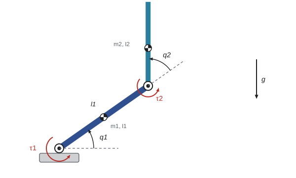
Working through the kinetic and potential energies (the center of mass of link 2 is at \( l_1(\cos q_1, \sin q_1) + l_{c2}(\cos(q_1 + q_2), \sin(q_1 + q_2)) \)) and applying the Euler–Lagrange equations gives, with the shorthand \( c_2 = \cos q_2 \), \( s_2 = \sin q_2 \) and \( c_{12} = \cos(q_1 + q_2) \):
Three constants \( \alpha, \beta, \delta \) capture all the inertial parameters. The inertia felt by the shoulder, \( \alpha + 2\beta\cos q_2 \), is largest when the elbow is straight (\( q_2 = 0 \)) and smallest when it is folded, so the same shoulder motor sees a load that varies by a factor of two or more as the elbow moves.
Worked problem
Evaluating the inertia matrix
A two-link arm has \( m_1 = 3 \) kg, \( m_2 = 2 \) kg, \( l_1 = 0.4 \) m, \( l_{c1} = 0.2 \) m, \( l_{c2} = 0.15 \) m, \( I_1 = 0.04 \) kg·m² and \( I_2 = 0.015 \) kg·m². Find M with the elbow straight and with it at 90°.
Show solution
- \( \alpha = 0.04 + 0.015 + 3(0.04) + 2(0.16 + 0.0225) = 0.055 + 0.12 + 0.365 = 0.540 \).
- \( \beta = 2 \times 0.4 \times 0.15 = 0.12 \); \( \delta = 0.015 + 2 \times 0.0225 = 0.060 \).
- Elbow straight, \( c_2 = 1 \): \( M = \begin{bmatrix} 0.78 & 0.18 \\ 0.18 & 0.06 \end{bmatrix} \) kg·m².
- Elbow at 90°, \( c_2 = 0 \): \( M = \begin{bmatrix} 0.54 & 0.06 \\ 0.06 & 0.06 \end{bmatrix} \) kg·m².
Answer: The shoulder inertia falls from 0.78 to 0.54 kg·m² as the elbow bends, and the coupling term from 0.18 to 0.06. A shoulder controller tuned for one configuration therefore behaves differently in the other: about 20 % slower (since the natural frequency scales as \( 1/\sqrt{M_{11}} \)) when the arm is stretched out.
Interpreting the Coriolis, centrifugal and gravity terms
The vector \( \mathbf{C}(\mathbf{q},\dot{\mathbf{q}})\dot{\mathbf{q}} \) collects velocity-product torques. Terms in a single squared rate, such as \( \beta s_2\dot{q}_1^2 \) at the elbow, are centrifugal: when the shoulder swings quickly, link 2 is flung outward and the elbow must resist it. Terms in a product of two different rates, such as \( -2\beta s_2\dot{q}_1\dot{q}_2 \) at the shoulder, are Coriolis torques that arise when one joint's motion changes the moment arm of another link's moving mass. These terms grow with the square of speed, so they matter for fast robots and fade at low speed. The gravity vector \( \mathbf{g}(\mathbf{q}) \) depends only on configuration; it is the torque each joint needs to hold the arm still, and the first term in the shoulder entry includes the weight of link 2 acting at the elbow.
Worked problem
Gravity and centrifugal torques
For the arm of the previous example with \( q_1 = 0 \) (link 1 horizontal) and \( q_2 = 90° \) (link 2 pointing up), find the static gravity torques, and the extra elbow torque when the shoulder swings at 3 rad/s.
Show solution
- \( c_{12} = \cos 90° = 0 \), so link 2 contributes no torque about the elbow: \( g_2 = 0 \).
- Shoulder: \( g_1 = (3 \times 0.2 + 2 \times 0.4) \times 9.81 \times 1 + 0 = 1.4 \times 9.81 = 13.7 \) N·m.
- Centrifugal elbow torque: \( \beta s_2\dot{q}_1^2 = 0.12 \times 1 \times 9 = 1.08 \) N·m.
Answer: The shoulder needs 13.7 N·m to hold the arm, the elbow none, because link 2 is balanced over its joint. Swinging the shoulder at 3 rad/s demands an extra 1.08 N·m at the elbow just to keep link 2 from being flung outward, a torque a gravity-only model would miss.
The manipulator equation and its properties
For any serial manipulator, rigid links and ideal joints, the Euler–Lagrange equations produce the same structure:
Friction, actuator dynamics and contact forces are added to this core model in later lessons. Its properties are what make robot control theory possible:
- M(q) is symmetric and positive definite, so it is always invertible: \( \ddot{\mathbf{q}} = \mathbf{M}^{-1}(\boldsymbol{\tau} - \mathbf{C}\dot{\mathbf{q}} - \mathbf{g}) \), the forward dynamics used in simulation.
- M(q) is bounded above and below for revolute arms, so the inertia never becomes zero or infinite.
- With C defined through Christoffel symbols, the matrix \( \dot{\mathbf{M}} - 2\mathbf{C} \) is skew-symmetric. Physically this expresses energy conservation: the Coriolis and centrifugal forces do no net work. It is the key step in stability proofs for many robot controllers.
- The dynamics are linear in a set of inertial parameters (masses, first moments, inertias), so \( \mathbf{M}\ddot{\mathbf{q}} + \mathbf{C}\dot{\mathbf{q}} + \mathbf{g} = \mathbf{Y}(\mathbf{q},\dot{\mathbf{q}},\ddot{\mathbf{q}})\boldsymbol{\theta} \). This makes parameter identification a least-squares problem and underpins adaptive control (lesson 11).
The Christoffel definition gives each element of C as \( C_{kj} = \sum_i \tfrac{1}{2}\left(\frac{\partial M_{kj}}{\partial q_i} + \frac{\partial M_{ki}}{\partial q_j} - \frac{\partial M_{ij}}{\partial q_k}\right)\dot{q}_i \). For the two-link arm it yields \( \mathbf{C} = \beta s_2\begin{bmatrix} -\dot{q}_2 & -(\dot{q}_1 + \dot{q}_2) \\ \dot{q}_1 & 0 \end{bmatrix} \), which reproduces the vector given earlier.
Worked problem
Checking skew symmetry
Verify that \( \dot{\mathbf{M}} - 2\mathbf{C} \) is skew-symmetric for the two-link arm.
Show solution
- \( \dot{\mathbf{M}} = -\beta s_2\dot{q}_2\begin{bmatrix} 2 & 1 \\ 1 & 0 \end{bmatrix} \), since only \( c_2 \) varies.
- \( 2\mathbf{C} = \beta s_2\begin{bmatrix} -2\dot{q}_2 & -2\dot{q}_1 - 2\dot{q}_2 \\ 2\dot{q}_1 & 0 \end{bmatrix} \).
- Subtract: \( \dot{\mathbf{M}} - 2\mathbf{C} = \beta s_2\begin{bmatrix} 0 & 2\dot{q}_1 + \dot{q}_2 \\ -2\dot{q}_1 - \dot{q}_2 & 0 \end{bmatrix} \).
Answer: The result has zero diagonal and opposite off-diagonal entries, so it is skew-symmetric, and \( \mathbf{x}^{\mathsf{T}}(\dot{\mathbf{M}} - 2\mathbf{C})\mathbf{x} = 0 \) for any vector. This is the energy-conservation property in matrix form.
Forward dynamics and simulation
Inverse dynamics computes the torque for a desired motion; forward dynamics computes the motion produced by given torques by solving the manipulator equation for \( \ddot{\mathbf{q}} \) and integrating. The code below implements both for the two-link arm. It first computes the torque needed to hold a configuration, then releases the arm with zero torque and integrates the motion with a fourth-order Runge–Kutta step, checking that total energy is conserved, a standard test that a dynamic model has been coded correctly.
import numpy as np
m1, m2, l1, lc1, lc2, I1, I2, g = 3, 2, 0.4, 0.2, 0.15, 0.04, 0.015, 9.81
a = I1 + I2 + m1*lc1**2 + m2*(l1**2 + lc2**2); b = m2*l1*lc2; d = I2 + m2*lc2**2
def M(q):  return np.array([[a + 2*b*np.cos(q[1]), d + b*np.cos(q[1])], [d + b*np.cos(q[1]), d]])
def Cqd(q, qd):
    s = np.sin(q[1]); return np.array([-b*s*(2*qd[0]*qd[1] + qd[1]**2), b*s*qd[0]**2])
def G(q):
    c1, c12 = np.cos(q[0]), np.cos(q[0] + q[1])
    return np.array([(m1*lc1 + m2*l1)*g*c1 + m2*lc2*g*c12, m2*lc2*g*c12])
def energy(q, qd):
    V = (m1*lc1 + m2*l1)*g*np.sin(q[0]) + m2*lc2*g*np.sin(q[0] + q[1])
    return 0.5*qd @ M(q) @ qd + V
q0 = np.array([0.0, np.pi/2])
print("holding torque (N m):", np.round(G(q0), 3))
def f(x, tau):
    q, qd = x[:2], x[2:]
    qdd = np.linalg.solve(M(q), tau - Cqd(q, qd) - G(q))
    return np.concatenate([qd, qdd])
x, h = np.array([0.0, 0.3, 0.0, 0.0]), 1e-3
E0 = energy(x[:2], x[2:])
for k in range(2000):                    # 2 s with zero torque (arm falls freely)
    k1 = f(x, 0); k2 = f(x + h/2*k1, 0); k3 = f(x + h/2*k2, 0); k4 = f(x + h*k3, 0)
    x = x + h/6*(k1 + 2*k2 + 2*k3 + k4)
print("q after 2 s (rad):", np.round(x[:2], 3))
print(f"energy drift: {energy(x[:2], x[2:]) - E0:.2e} J")holding torque (N m): [13.734 0. ] q after 2 s (rad): [-1.848 -0.156] energy drift: -8.51e-09 J
The holding torques match the hand calculation, and with no friction or input the total energy stays constant to within about 10⁻⁸ J over two seconds of chaotic double-pendulum motion. A drift of joules would signal an error in M, C or g, or a time step that is too large.
Scaling up: real robots
A six-axis industrial arm has a 6 × 6 inertia matrix whose entries are long trigonometric expressions in all six angles. Nobody writes them out by hand. Robotics libraries build the model from a URDF or similar description and compute inverse dynamics with the recursive Newton–Euler algorithm, forward dynamics with the articulated-body algorithm, and the inertia matrix itself with the composite rigid-body algorithm, all in time roughly proportional to the number of links. The value of the Lagrangian derivation is conceptual: it reveals the structure, symmetric positive-definite inertia, velocity-squared coupling, configuration-dependent gravity and linearity in parameters, that controllers exploit regardless of how the numbers are computed. Model parameters from CAD are usually refined by identification experiments in which the robot follows exciting trajectories while joint torques are measured, and the parameter vector is found by least squares using the linear-in-parameters property.
Common mistakes
MistakeForgetting that the inertia matrix depends on configuration
InsteadM(q) changes with joint angles; evaluate it at the current q.
MistakeDropping Coriolis and centrifugal terms in fast motions
InsteadThey scale with velocity squared and can be large at speed.
MistakeMeasuring the second joint angle absolutely when the formula uses a relative angle
InsteadUse the same angle convention as the derivation, here \( q_2 \) relative to link 1.
MistakeSimulating with a time step too large and trusting the result
InsteadCheck energy conservation or halve the step to confirm the answer does not change.
MistakeIncluding constraint forces at the joints in a Lagrangian derivation
InsteadIdeal joint constraint forces do no work and drop out automatically.
Summary and key terms
- The Lagrangian \( \mathcal{L} = T - V \) and the Euler–Lagrange equations give equations of motion without joint reaction forces.
- Kinetic energy of a manipulator is \( \tfrac{1}{2}\dot{\mathbf{q}}^{\mathsf{T}}\mathbf{M}(\mathbf{q})\dot{\mathbf{q}} \), defining the symmetric positive-definite inertia matrix.
- Every serial arm obeys \( \mathbf{M}\ddot{\mathbf{q}} + \mathbf{C}\dot{\mathbf{q}} + \mathbf{g} = \boldsymbol{\tau} \).
- For the two-link arm, three constants α, β, δ capture the inertial parameters, and shoulder inertia varies as \( \alpha + 2\beta\cos q_2 \).
- Centrifugal terms involve squared rates; Coriolis terms involve products of different rates; gravity depends only on configuration.
- \( \dot{\mathbf{M}} - 2\mathbf{C} \) is skew-symmetric, and the dynamics are linear in inertial parameters.
- Forward dynamics solves for acceleration and integrates; an energy check validates a model.
- Generalized coordinates
- Independent variables, here joint angles, that fix the configuration.
- Lagrangian
- Kinetic minus potential energy.
- Euler–Lagrange equations
- The differential equations derived from the Lagrangian for each coordinate.
- Generalized force
- The torque or force associated with a generalized coordinate.
- Inertia matrix
- The configuration-dependent matrix M(q) in \( T = \tfrac{1}{2}\dot{q}^{\mathsf{T}}M\dot{q} \).
- Coriolis torque
- A velocity-product torque involving two different joint rates.
- Centrifugal torque
- A velocity-product torque involving the square of a joint rate.
- Gravity vector
- The configuration-dependent torque g(q) needed to hold the robot still.
- Forward dynamics
- Computing accelerations, and by integration motion, from applied torques.
- Linearity in parameters
- The property that the dynamics equal a known regressor times a parameter vector.
Practice problems
Work each problem on paper first, then reveal the answer to check.
Write the Lagrangian of a mass m on a spring k moving along x.
Show answer
\( \tfrac{1}{2}m\dot{x}^2 - \tfrac{1}{2}kx^2 \).
Apply Euler–Lagrange to that Lagrangian with applied force F.
Show answer
\( m\ddot{x} + kx = F \).
Is the inertia matrix ever singular for a real arm?
Show answer
No; it is positive definite in every configuration.
For the example arm, what is \( M_{11} \) at \( q_2 = 180° \)?
Show answer
\( 0.54 - 0.24 = 0.30 \) kg·m².
Which term in the two-link elbow equation is centrifugal?
Show answer
\( \beta s_2\dot{q}_1^2 \).
What property of M allows simulation by solving for \( \ddot{q} \)?
Show answer
It is always invertible because it is positive definite.
At low speeds, which terms can usually be neglected?
Show answer
The Coriolis and centrifugal terms, which scale with velocity squared.
Find \( g_2 \) for the example arm with \( q_1 + q_2 = 0 \).
Show answer
\( 2 \times 0.15 \times 9.81 = 2.94 \) N·m.
Why is linearity in parameters useful?
Show answer
Unknown inertial parameters can be estimated by least squares and adapted online.
A simulated frictionless arm gains 5 J of energy in 1 s with no input. What does that suggest?
Show answer
A modeling error or too large an integration step.
Lesson quiz · 5 questions
Score 60% or more to complete this lesson.
Create a free account to save your progress, take quizzes and earn a certificate.