
ROB-420 · Lesson 6 of 12 · 29 min
Quadrotor dynamics and control
Drones, or uncrewed aircraft systems, have become one of the most widespread kinds of autonomous robot. Multirotors in particular, with four or more fixed-pitch propellers, are mechanically simple: their only moving parts are the motors. Yet they are inherently unstable and can be flown only with fast feedback control. This lesson develops the physics of a quadrotor: how thrust and torque from the rotors produce translation and rotation, how much power hovering takes and how long a battery lasts, and how a cascaded controller of the kind found in open-source autopilots stabilizes attitude and tracks position. We describe the PX4 and ArduPilot autopilots generically; both are widely used, open-source flight stacks with similar layered designs.
Thrust, torque and the four control inputs
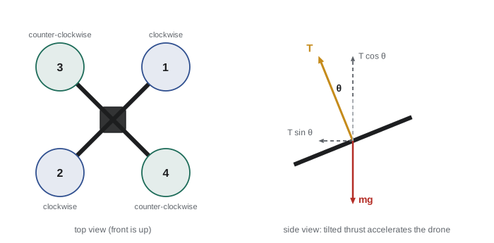
Each rotor produces thrust approximately proportional to the square of its angular speed, \( T_i = k_T\omega_i^2 \), and a reaction torque about its axis, \( Q_i = k_Q\omega_i^2 \), opposite to its spin. In a quadrotor, two rotors spin clockwise and two counter-clockwise so that, in hover, their reaction torques cancel. By changing individual rotor speeds the flight controller commands four quantities: total thrust along the body's vertical axis, roll torque, pitch torque and yaw torque. A quadrotor in the X configuration with arm length \( l \) has a mixer that maps these to motor commands.
The vehicle is underactuated: it has six degrees of freedom but only four inputs. It cannot accelerate sideways without first tilting. To move forward, it pitches nose down so that part of its thrust points backward, accelerating it forward. Translation is therefore controlled through attitude, which is why the attitude loop must be fast and accurate.
Hover thrust and power
In hover, total thrust equals weight: \( T = mg \). Tilted by angle \( \theta \) in steady level flight, the vertical component must still equal weight, so \( T = mg/\cos\theta \), and horizontal acceleration is \( g\tan\theta \). Momentum theory from aerodynamics gives the ideal power required to hover with a rotor disk area \( A \) in air of density \( \rho \):
Power grows with the 1.5 power of weight and falls with larger rotor area, which is why heavy-lift drones have large, slow propellers. Cold air is denser, slightly reducing hover power, but cold batteries deliver less energy, a real constraint for winter operations. Endurance is usable battery energy divided by electrical power, after accounting for motor and propeller efficiency and a reserve.
# Quadrotor hover thrust, ideal and electrical power, and endurance
import numpy as np
m, g, rho = 2.0, 9.81, 1.225             # 2 kg drone, sea-level air
D, n_rot = 0.30, 4                         # 30 cm propellers, four rotors
A = n_rot * np.pi * (D / 2)**2             # total disk area
T = m * g
P_ideal = T**1.5 / np.sqrt(2 * rho * A)
FM, eta_motor = 0.6, 0.8                   # figure of merit, motor+ESC efficiency
P_elec = P_ideal / FM / eta_motor
E_batt = 4 * 3.7 * 5.0                     # 4S, 5 Ah pack in Wh
usable = 0.8                               # keep 20 % reserve
endurance_min = E_batt * usable / P_elec * 60
print(f"hover thrust {T:5.1f} N  ({T / n_rot:4.2f} N per rotor)")
print(f"ideal power {P_ideal:5.1f} W, electrical power {P_elec:5.1f} W")
print(f"battery {E_batt:4.0f} Wh, hover endurance {endurance_min:4.1f} min")
for cold_frac in (0.8, 0.6):
    print(f"  with {cold_frac:.0%} capacity in cold: {endurance_min * cold_frac:4.1f} min")
tilt = np.radians(20)
print(f"20 deg tilt: thrust {T / np.cos(tilt):5.1f} N, horizontal accel {g * np.tan(tilt):4.2f} m/s^2")hover thrust 19.6 N (4.91 N per rotor) ideal power 104.4 W, electrical power 217.5 W battery 74 Wh, hover endurance 16.3 min with 80% capacity in cold: 13.1 min with 60% capacity in cold: 9.8 min 20 deg tilt: thrust 20.9 N, horizontal accel 3.57 m/s^2
Worked problem
Hover thrust per motor and tilt limit
A 1.5 kg quadrotor has motors that can each produce at most 8 N of thrust. What fraction of maximum thrust does it use in hover, and what is the largest tilt angle at which it can hold altitude?
Show solution
- Weight: \( 1.5 \times 9.81 = 14.7 \) N; per motor 3.68 N.
- Hover fraction: \( 3.68 / 8 = 0.46 \), a thrust-to-weight ratio of about 2.2.
- Maximum total thrust 32 N; holding altitude requires \( T\cos\theta = 14.7 \), so \( \cos\theta = 0.46 \) and \( \theta \approx 63^\circ \).
- In practice controllers leave margin for attitude control, so tilt is limited to perhaps 35 to 45 degrees.
Answer: Hover uses about 46 % of maximum thrust; altitude can be held up to about 63 degrees of tilt in theory, but tilt is limited well below that to keep control authority.
Rigid-body dynamics
The translational dynamics in the world frame are Newton's law: mass times acceleration equals the thrust vector, rotated from body to world frame by the rotation matrix \( R \), plus gravity and drag. The rotational dynamics are Euler's equation: inertia times angular acceleration plus the gyroscopic term equals the applied torques. ROB-210 and ROB-310 introduced these equations.
Small quadrotors have low rotational inertia, so they respond to torque within tens of milliseconds. That agility is a blessing for control but means that a sensor or software fault becomes a crash within a fraction of a second. There is no gliding fallback as with a fixed-wing aircraft.
Cascaded control
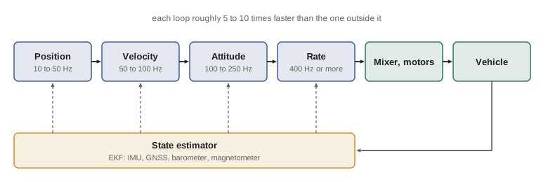
Autopilots for multirotors use a cascade of loops, each faster than the one outside it. The innermost rate loop, running at several hundred hertz up to a kilohertz or more, controls body angular rates measured by the gyroscopes using PID control. Around it, the attitude loop, often a proportional controller on attitude error expressed with quaternions, outputs rate set points. Around that, the velocity loop computes the desired acceleration and therefore the desired tilt and total thrust, and the outermost position loop outputs velocity set points. Navigation and mission logic sit above. Each loop treats the inner loop as a fast, nearly ideal actuator; the rule of thumb is that each inner loop should be roughly five to ten times faster in bandwidth than the next outer loop.
| Loop | Input | Output | Typical rate |
|---|---|---|---|
| Position | Position set point and estimate | Velocity set point | 10 to 50 Hz |
| Velocity | Velocity set point and estimate | Desired acceleration, tilt and thrust | 50 to 100 Hz |
| Attitude | Attitude set point and estimate | Angular rate set point | 100 to 250 Hz |
| Rate | Rate set point and gyroscope | Torque commands to mixer | 400 Hz to several kHz |
State estimation, usually an extended Kalman filter, fuses the IMU with a barometer, magnetometer, GNSS and optionally optical flow, a downward rangefinder or visual-inertial odometry, as in ROB-340. Autopilots provide flight modes such as stabilized, in which the pilot commands attitude; altitude hold; position hold; and fully autonomous mission. Failsafes trigger return-to-launch or landing on low battery, loss of the command link or loss of GNSS, and geofences keep the vehicle inside a permitted area.
# Single-axis cascaded control: attitude P loop around a rate PID loop on a quadrotor roll axis
import numpy as np
J, dt = 0.02, 0.002                        # roll inertia kg m^2, 500 Hz rate loop
kp_att = 6.0                               # attitude loop gain (1/s)
kp, ki, kd = 0.30, 0.20, 0.004             # rate PID gains
phi = rate = integ = prev_err = 0.0
phi_ref = np.radians(15)                   # step to 15 deg roll
log = []
for k in range(int(1.5 / dt)):
    rate_ref = kp_att * (phi_ref - phi)                 # outer loop
    err = rate_ref - rate
    integ += err * dt
    tau = kp * err + ki * integ + kd * (err - prev_err) / dt
    prev_err = err
    tau = np.clip(tau, -0.5, 0.5)                       # torque limit
    rate += tau / J * dt
    phi += rate * dt
    log.append(np.degrees(phi))
log = np.array(log)
t90 = np.argmax(log >= 0.9 * 15) * dt
print(f"rise to 90 %: {t90 * 1000:.0f} ms, overshoot {max(0, log.max() - 15):.2f} deg, final {log[-1]:.2f} deg")rise to 90 %: 316 ms, overshoot 0.48 deg, final 15.02 deg
Disturbances and robustness
Wind is the main disturbance for small drones. A gust changes the relative airflow, producing drag and moments, and blade flapping makes the effect more complex. Integral action in the velocity loop rejects steady wind, and some controllers estimate wind explicitly. Other hazards include vibration that corrupts IMU readings, magnetic interference near steel structures that confuses the compass, propeller damage, motor failure and icing on rotors, which can quickly reduce thrust in freezing drizzle. Hexacopters and octocopters can survive a single motor failure; a quadrotor generally cannot hold yaw after losing a motor, although research controllers can land it by letting it spin.
Worked problem
Tilt needed to hold position in wind
A drone with frontal drag coefficient times area \( C_dA = 0.04 \) m² hovers in a steady 10 m/s wind. Air density is 1.225 kg/m³ and mass 2 kg. What tilt angle is needed to hold position?
Show solution
- Drag: \( F = \tfrac{1}{2}\rho C_dA v^2 = 0.5 \times 1.225 \times 0.04 \times 100 = 2.45 \) N.
- Horizontal thrust component must equal 2.45 N while the vertical component equals \( 19.6 \) N.
- \( \tan\theta = 2.45/19.6 = 0.125 \), so \( \theta \approx 7.1^\circ \).
Answer: About 7 degrees into the wind, with thrust increased slightly to 19.8 N. Power and endurance suffer as wind rises, and gusts demand control margin.
Beyond the quadrotor
Multirotors trade efficiency for simplicity and hovering ability. A fixed-wing aircraft generates lift from its wing and needs power only to overcome drag, so it can fly several times longer and farther on the same battery, but it cannot hover and needs space to take off and land. Hybrid vertical take-off and landing designs combine the two: a tilt-rotor or a quadplane, with separate lift rotors for take-off and a pusher propeller for cruise, takes off like a multirotor and transitions to wing-borne flight. Transition is the hardest phase to control, because the aircraft passes through speeds where neither the rotors nor the wing alone carry it comfortably. Autopilots such as PX4 and ArduPilot support these configurations with additional control allocation logic, and long-range delivery and mapping drones increasingly use them. Helicopter-style single-rotor drones and lighter-than-air platforms fill other niches, such as heavy payloads or very long endurance.
Worked problem
Endurance of a fixed wing versus a multirotor
A 2 kg fixed-wing drone with lift-to-drag ratio 10 cruises at 15 m/s. Propulsive efficiency is 0.5. Compare its electrical power with the 217 W hover power of the 2 kg quadrotor in this lesson.
Show solution
- Drag in level flight: \( mg/(L/D) = 19.6/10 = 1.96 \) N.
- Mechanical power: \( 1.96 \times 15 = 29.4 \) W.
- Electrical power: \( 29.4/0.5 = 59 \) W.
Answer: About 59 W, less than a third of the multirotor's hover power, so the fixed wing flies over three times as long on the same battery, at the cost of being unable to hover.
Common mistakes
MistakeThinking a quadrotor can move sideways without tilting.
InsteadIt is underactuated; horizontal acceleration requires tilting the thrust vector.
MistakeDesigning an outer loop as fast as the inner loop.
InsteadEach inner loop should be several times faster than the next outer loop.
MistakeQuoting endurance from room-temperature battery capacity in winter.
InsteadCold batteries deliver less energy; derate and keep a reserve.
MistakeFlying at maximum thrust-to-weight margin.
InsteadHover should use well under maximum thrust to keep authority for control and gusts.
MistakeAssuming a quadrotor survives a motor failure.
InsteadGenerally it cannot maintain controlled flight; use redundancy for critical missions.
Summary and key terms
- Rotor thrust and torque scale with the square of rotor speed; a mixer maps thrust and torques to motors.
- Quadrotors are underactuated and accelerate horizontally by tilting.
- Hover power scales with weight to the 1.5 power and falls with rotor area.
- Endurance depends on usable battery energy, efficiency, reserve and temperature.
- Cascaded loops (position, velocity, attitude, rate) each run faster than the one outside.
- An EKF fuses IMU, barometer, magnetometer and GNSS; failsafes and geofences protect against faults.
- Wind, vibration, magnetic interference, icing and motor failure are key hazards.
- Multirotor
- An aircraft lifted and controlled by several fixed-pitch rotors.
- Mixer
- The mapping from thrust and torque commands to individual motor commands.
- Underactuated
- Having fewer independent inputs than degrees of freedom.
- Momentum theory
- An aerodynamic model relating rotor thrust to induced power.
- Figure of merit
- Ratio of ideal to actual hover power for a rotor.
- Rate loop
- The innermost loop, controlling body angular rates.
- Cascaded control
- Nested feedback loops where each outer loop sets the inner loop's reference.
- Failsafe
- An automatic response to a fault, such as returning to launch.
- Geofence
- A virtual boundary the vehicle is not allowed to cross.
- Thrust-to-weight ratio
- Maximum thrust divided by weight.
Practice problems
Work each problem on paper first, then reveal the answer to check.
If rotor speed doubles, thrust changes by what factor?
Show answer
Four.
Why do quadrotors use pairs of counter-rotating rotors?
Show answer
To cancel reaction torques so yaw can be controlled.
Horizontal acceleration at 30 degrees of tilt in level flight?
Show answer
\( g\tan 30^\circ \approx 5.7 \) m/s².
Doubling weight changes ideal hover power by what factor?
Show answer
\( 2^{1.5} \approx 2.8 \).
Endurance for 60 Wh usable at 300 W?
Show answer
12 minutes.
Which loop runs fastest?
Show answer
The rate loop.
Name three sensors a multirotor EKF fuses.
Show answer
IMU, barometer, magnetometer, GNSS, optical flow or rangefinder.
Name two failsafe triggers.
Show answer
Low battery, lost command link, lost GNSS or geofence breach.
Why is icing dangerous for drones?
Show answer
Ice on rotors reduces thrust and adds weight.
Advantage of a hexacopter over a quadrotor?
Show answer
It can tolerate a single motor failure.
Lesson quiz · 5 questions
Score 60% or more to complete this lesson.
Create a free account to save your progress, take quizzes and earn a certificate.