
ROB-430 · Lesson 6 of 12 · 31 min
Teleoperation and shared autonomy
Teleoperation means operating a robot from a distance. It is used wherever full autonomy is not yet reliable enough or where human judgment is essential: bomb disposal, nuclear decommissioning, undersea work, space, search and rescue, remote inspection, drone flight and surgery. It is also the backbone of many systems that are described as autonomous, since remote operators often stand by to help robots that get stuck. This lesson covers the architecture of teleoperation, the effects of time delay, the role of haptic feedback, the situation awareness problems of seeing the world through a robot's cameras, and shared autonomy, in which human and robot control are blended. It ends with a factual look at robotic surgical systems.
Architecture and control modes
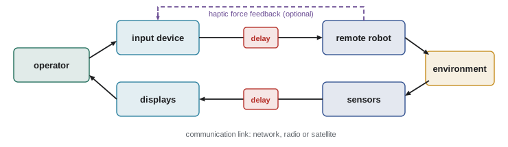
A teleoperation system has an operator station, a communication link and a remote robot. The operator station provides displays (camera views, maps, sensor readouts) and input devices (joysticks, gamepads, haptic arms, touchscreens or a replica of the robot arm). Traditionally the operator's device was called the master and the remote robot the slave; current usage prefers leader and follower, or operator side and remote side. The remote robot executes commands and sends back sensor data.
Input mappings fall into two main types. In position control, the robot's position follows the input device's position: move the handle 5 cm and the robot moves 5 cm, or a scaled amount. This is natural for manipulation within a limited workspace. In rate control, the input sets velocity: push the joystick forward and the robot drives forward at a speed proportional to the deflection. Rate control suits mobile robots and large workspaces but is harder for precise positioning. Motion scaling maps large operator movements to small robot movements for precision, or the reverse for reach, and indexing, or clutching, lets operators reposition the input device without moving the robot, like lifting a mouse.
Worked problem
Motion scaling for fine work
A surgeon's hand tremor has an amplitude of about 0.2 mm at 8 to 12 Hz. The system applies 3:1 motion scaling and a low-pass filter that reduces the tremor amplitude by a further factor of 10. What tremor amplitude reaches the instrument tip?
Show solution
- Scaling: \( 0.2/3 \approx 0.067 \) mm.
- Filtering: \( 0.067/10 \approx 0.0067 \) mm, about 7 micrometers.
Answer: About 7 micrometers, which shows why scaling and filtering make fine dissection feasible; the trade-off is that larger hand movements are needed and the filter adds a small lag.
The effects of time delay
Delay is the defining challenge of teleoperation. Signals take time to travel and to be processed, encoded, transmitted and displayed. A robot on the same local network might have a round-trip delay of tens of milliseconds; a robot controlled over the internet across a continent, roughly 50 to 150 ms; through a geostationary satellite, more than half a second; on the Moon, about 2.6 s; and on Mars, between about 6 and 44 minutes depending on the planets' positions. Video encoding and buffering often add more delay than the network itself.
Research since the 1960s, starting with William Ferrell's experiments at MIT, showed that as delay grows, operators abandon continuous control and adopt a move-and-wait strategy: make a small move, wait to see the result, then make the next move. Task completion time then grows roughly in proportion to the delay multiplied by the number of moves needed. Delays of a few hundred milliseconds already noticeably degrade performance in continuous tracking and driving tasks, and operators also overcorrect, producing oscillations.
Worked problem
Delay on a remote manipulation task
An operator needs about 12 corrective moves of 1.5 s each to insert a tool into a socket with no delay. Estimate the completion time with a round-trip delay of 0.5 s and with the 2.6 s Earth-Moon delay, assuming a move-and-wait strategy.
Show solution
- No delay: \( 12 \times 1.5 = 18 \) s.
- With 0.5 s: \( 12 \times (1.5 + 0.5) = 24 \) s.
- With 2.6 s: \( 12 \times (1.5 + 2.6) \approx 49 \) s.
Answer: About 18, 24 and 49 s; longer delays also increase the number of moves, because each one is made with staler information, so these are optimistic estimates.
# Move-and-wait simulation: moves needed and time to reach a 2 mm target with delay
import numpy as np
rng = np.random.default_rng(430)
def trial(delay, gain=0.5, noise=0.3, t_move=1.0, tol=2.0, start=60.0):
    err, t, moves = start, 0.0, 0
    while abs(err) > tol and moves < 200:
        err -= gain * err * (1 + rng.normal(0, noise))    # each move removes most of the error
        t += t_move + delay; moves += 1
    return moves, t
for d in (0.0, 0.3, 1.0, 2.6):
    res = np.array([trial(d) for _ in range(300)])
print(f"delay {d:3.1f} s: mean moves {res[:,0].mean():4.1f}, mean time {res[:,1].mean():5.1f} s")delay 0.0 s: mean moves 5.1, mean time 5.1 s delay 0.3 s: mean moves 5.1, mean time 6.7 s delay 1.0 s: mean moves 5.2, mean time 10.5 s delay 2.6 s: mean moves 5.2, mean time 18.6 s
Several techniques reduce the impact of delay. Predictive displays overlay a simulated model of the robot that responds immediately to commands, showing where the robot will be once the delayed video catches up. Supervisory control, as introduced in lesson 1, raises the level of commands: instead of steering continuously, the operator specifies a goal or a waypoint and the robot executes it locally, so delay affects only how quickly new goals arrive. Planetary rovers work this way, receiving sequences of commands once or twice per day. Model-mediated teleoperation builds a local model of the remote environment so that interaction forces can be rendered without waiting for the round trip.
Haptic feedback
Haptic feedback conveys forces and touch from the remote side to the operator. In bilateral teleoperation, the operator's device both commands motion and displays forces sensed at the robot. A system is called transparent if the operator feels as if directly touching the remote environment. Haptics improve performance in tasks such as inserting parts, palpating tissue or avoiding excessive force. However, with time delay, direct force feedback can make the loop unstable: energy injected by delayed forces can cause growing oscillations. Methods based on passivity theory, such as wave variables and time-domain passivity control, keep the system stable by ensuring it never generates energy, at some cost in transparency. Lighter alternatives include vibrotactile cues on a handle or wristband and visual force displays.
| Feedback type | What the operator gets | Advantages | Limitations |
|---|---|---|---|
| Visual force display | Bar or color showing force on screen | Simple, stable with delay | Adds visual load; slow to interpret |
| Vibrotactile cue | Buzz on handle or wrist at contact or threshold | Cheap, stable, uses another channel | Conveys little magnitude or direction |
| Kinesthetic force feedback | Device pushes back with sensed force | Natural, improves fine manipulation | Costly; stability issues with delay |
| Haptic virtual fixtures | Device guides or blocks motion along planned paths | Improves precision and safety | Needs a model of the task and environment |
Virtual fixtures, introduced by Louis Rosenberg in the early 1990s, are software-generated constraints that guide the operator's motion, like a ruler guiding a pencil. A forbidden-region fixture stops the instrument from entering a protected zone; a guidance fixture pulls it toward a planned path. They are an early form of shared control.
Seeing through the robot
Teleoperators see the world through cameras that offer a narrow field of view, limited depth cues and a viewpoint that may not match the robot's body. Studies of rescue robot operators, including Jennifer Casper and Robin Murphy's account of robots used in the rescue response after the September 11, 2001 attacks in New York, found that operators spent much of their time trying to understand where the robot was and what state it was in, rather than searching. Common problems include the keyhole effect of a narrow view, losing track of the robot's orientation, misjudging distances and gaps, not noticing that the robot is tilted, and failing to see obstacles just outside the frame. Remedies include wider or multiple cameras, a view of the robot itself from an external or overhead camera, maps with the robot's position and heading, attitude indicators, and fusing sensor data into a single integrated display. Lesson 2's situation awareness measures can be used to compare interfaces.
Shared autonomy
Shared autonomy combines human input with robot autonomy continuously rather than switching between them. A common formulation is policy blending, analyzed by Anca Dragan and Siddhartha Srinivasa in 2013. The robot infers the user's likely goal from their input so far, computes its own command toward that goal, and blends it with the user's command:
The arbitration weight \( \alpha \) typically rises with the robot's confidence in its goal prediction. When the robot is unsure, the user is in control; when it is confident, it provides more help. Dragan and Srinivasa found that users preferred aggressive assistance when the robot's prediction was right but disliked it strongly when the robot was confidently wrong. Later approaches model assistance as decision-making under uncertainty about the user's goal, providing help that is useful for all likely goals at once. Shared autonomy is especially valuable for assistive robot arms controlled through low-dimensional interfaces such as a two-axis joystick or a sip-and-puff switch, where controlling six or seven joints directly would be exhausting.
Worked problem
Blending commands
A user pushes the joystick so that the commanded velocity is \( (0.10, 0.02) \) m/s. The robot predicts the goal is a cup and would command \( (0.08, 0.06) \) m/s. With confidence high enough that \( \alpha = 0.6 \), what is the blended command?
Show solution
- Robot part: \( 0.6 \times (0.08, 0.06) = (0.048, 0.036) \).
- User part: \( 0.4 \times (0.10, 0.02) = (0.040, 0.008) \).
- Sum: \( (0.088, 0.044) \) m/s.
Answer: About \( (0.088, 0.044) \) m/s: the user's intent still dominates the forward direction while the robot steers toward the cup.
# Policy blending toward two possible goals with confidence-based arbitration
import numpy as np
rng = np.random.default_rng(430)
goals = np.array([[0.5, 0.4], [0.5, -0.4]]); true_goal = 0
x = np.zeros(2); dt = 0.1; belief = np.array([0.5, 0.5])
for step in range(40):
    to_goal = goals[true_goal] - x
    u_h = 0.2 * to_goal / (np.linalg.norm(to_goal) + 1e-9) + rng.normal(0, 0.12, 2)   # noisy user
    for g in range(2):                                   # update belief from how well u_h points at each goal
        d = goals[g] - x; cos = d @ u_h / (np.linalg.norm(d) * np.linalg.norm(u_h) + 1e-9)
        belief[g] *= np.exp(0.6 * cos)
    belief /= belief.sum()
    conf = belief.max(); alpha = 0.8 / (1 + np.exp(-12 * (conf - 0.7)))
    d = goals[belief.argmax()] - x; u_r = 0.2 * d / (np.linalg.norm(d) + 1e-9)
    x = x + dt * (alpha * u_r + (1 - alpha) * u_h)
    if step in (2, 5, 10, 39):
print(f"step {step:2d}: P(goal 0) {belief[0]:.2f}, alpha {alpha:.2f}, pos ({x[0]:.2f}, {x[1]:.2f})")step 2: P(goal 0) 0.70, alpha 0.39, pos (0.09, 0.02) step 5: P(goal 0) 0.93, alpha 0.75, pos (0.14, 0.07) step 10: P(goal 0) 1.00, alpha 0.78, pos (0.21, 0.14) step 39: P(goal 0) 1.00, alpha 0.78, pos (0.50, 0.40)
Robotic surgery: a factual account
The best-known teleoperated robot in daily use is the da Vinci surgical system made by Intuitive Surgical, first cleared by the US Food and Drug Administration in 2000 for general laparoscopic surgery and since used in millions of procedures worldwide, including in many Canadian hospitals. Despite the name, it is not an autonomous robot. The surgeon sits at a console a few meters from the patient, viewing a magnified stereoscopic image from an endoscope, and moves hand controllers whose motions are scaled and tremor-filtered before being reproduced by wristed instruments inserted through small incisions. A patient-side team assists. For most of its history the system gave no direct force feedback, so surgeons learned to judge tissue tension visually; the da Vinci 5 model, cleared in 2024, introduced instruments with force feedback.
Evidence on clinical outcomes compared with conventional laparoscopic or open surgery varies by procedure. For some operations, robotic surgery is associated with shorter hospital stays or less blood loss, while for others large trials have found similar outcomes at higher cost. Training, case volume and cost are major factors, and surgical teams must adapt their communication because the surgeon at the console is physically separated from the patient and the bedside team. Long-distance telesurgery has been demonstrated, beginning with a 2001 gallbladder removal performed from New York on a patient in Strasbourg with a round-trip delay of about 155 ms, but it remains uncommon because of network reliability, delay and regulatory questions. Research into automating parts of surgical tasks, such as suturing, is active, but at the time of writing deployed systems leave the surgeon in direct control.
Designing an operator interface
Good teleoperation interfaces follow a few principles. Show the robot in its environment, not only the camera view. Keep the robot's orientation and state visible at all times. Match control mappings to the operator's frame of reference, so pushing forward moves the robot away from the camera view, not along some internal axis. Make delay visible, and use predictive displays or higher-level commands when it is large. Provide force or contact information appropriate to the task. Use shared autonomy to remove tedious low-level control, while making the robot's assistance visible so the operator knows what the robot is doing. And test with operators under realistic delay, lighting and stress, measuring task time, errors, workload and situation awareness.
# Measuring end-to-end video delay with a ROS 2 timestamp check (listing)
# On the robot, images carry a header stamp; on the operator station:
ros2 topic delay /camera/image_raw/compressed
# Typical output reports average, min and max delay in seconds over a window.
# Compare with network round trip:
ping -c 20 robot.local
# Video encoding and display usually add tens to hundreds of milliseconds on top of ping time.
Common mistakes
MistakeMeasuring network ping and calling it the system delay.
InsteadMeasure end-to-end delay from camera to display and from command to robot motion.
MistakeAdding strong force feedback to a delayed loop without stability analysis.
InsteadUse passivity-based methods, lower-bandwidth cues or local models when delay is significant.
MistakeGiving the operator only a forward camera view.
InsteadAdd maps, robot pose, attitude and external views to support situation awareness.
MistakeApplying aggressive assistance whenever the robot has a guess.
InsteadArbitrate by confidence and keep the user in control when predictions are uncertain.
MistakeDescribing surgical teleoperation systems as autonomous robots.
InsteadSystems such as da Vinci are surgeon-controlled; describe their autonomy accurately.
Summary and key terms
- Teleoperation links an operator station and a remote robot over a communication channel with delay.
- Position control suits manipulation; rate control suits mobile robots; scaling and clutching extend precision and reach.
- Delay leads to move-and-wait behavior and longer task times; predictive displays and supervisory control help.
- Haptic feedback improves contact tasks but needs stability methods when delay is present.
- Camera-based situation awareness is poor without maps, external views and pose displays.
- Shared autonomy blends human and robot commands, often with confidence-based arbitration.
- Surgical robots such as da Vinci are teleoperated, with scaling and tremor filtering; outcomes vary by procedure.
- Teleoperation
- Operating a robot from a distance through a communication link.
- Position control
- Input device position maps to robot position.
- Rate control
- Input device deflection maps to robot velocity.
- Move-and-wait
- A strategy of making small moves and waiting to see results under delay.
- Predictive display
- A display showing the predicted robot state before delayed feedback arrives.
- Bilateral teleoperation
- Teleoperation with force feedback from the remote side to the operator.
- Transparency
- How closely teleoperation feels like direct interaction with the environment.
- Virtual fixture
- A software constraint that guides or restricts operator motion.
- Shared autonomy
- Continuous blending of human and robot control.
- Arbitration
- The rule deciding how much weight robot and human commands receive.
Practice problems
Work each problem on paper first, then reveal the answer to check.
Which control mode is natural for driving a mobile robot?
Show answer
Rate control.
A 0.3 mm movement with 5:1 scaling gives what robot movement?
Show answer
0.06 mm.
10 moves of 2 s each with a 1 s round trip: move-and-wait time?
Show answer
30 s.
Approximate Earth-Moon round-trip delay?
Show answer
About 2.6 s.
Why can force feedback destabilize a delayed teleoperation loop?
Show answer
Delayed forces can inject energy and cause growing oscillations.
What does a predictive display show?
Show answer
A model of where the robot will be, responding immediately to commands.
With \( \alpha = 0.25 \), user command 1.0 and robot command 0.2, blended command?
Show answer
\( 0.25(0.2) + 0.75(1.0) = 0.8 \).
Name two remedies for the keyhole effect.
Show answer
Wider or multiple cameras, external views, maps or integrated displays.
When was da Vinci first cleared by the FDA?
Show answer
2000.
What is a forbidden-region virtual fixture?
Show answer
A constraint that stops an instrument from entering a protected zone.
Lesson quiz · 5 questions
Score 60% or more to complete this lesson.
Create a free account to save your progress, take quizzes and earn a certificate.