
ENGG-130 · Lesson 11 of 12 · 34 min
Moments of inertia of areas
Why are steel beams shaped like the letter I, floor joists set on edge rather than laid flat, and bicycle frames and flagpoles made of hollow tubes? The answer is a geometric property of a cross-section called its second moment of area, or area moment of inertia. Lesson 6 found the first moment of an area, ∫y dA, which locates the centroid. The second moment, ∫y² dA, measures how far an area is spread from an axis, and it controls how strongly a beam resists bending, how much it deflects, how much load a column can carry before it buckles, and where the resultant of fluid pressure acts on a submerged gate. This lesson defines the second moment, finds it for standard shapes by integration, introduces the parallel-axis theorem for composite sections, and shows why distributing material far from the centroid makes efficient structural members. It completes the statics toolkit that mechanics of materials builds on.
Definitions
For an area A in the x-y plane, the second moments about the x and y axes are:
Each element of area is weighted by the square of its distance from the axis, so area far from the axis counts much more than area near it. Second moments are always positive, have units of length to the fourth power (mm⁴ or m⁴), and depend on the axis chosen. Engineers most often need them about axes through the centroid.
Two related quantities are useful. The polar moment of inertia about an axis perpendicular to the plane through the origin is \(J_O = \int r^2\,dA = I_x + I_y\); it governs the twisting of circular shafts. The radius of gyration, \(k = \sqrt{I/A}\), is the distance at which the whole area could be concentrated to give the same second moment; it appears in column buckling formulas.
Do not confuse the area moment of inertia with the mass moment of inertia, ∫r² dm, which measures a body's resistance to angular acceleration in dynamics. They share a name and a form, but one is a property of a shape and the other of a mass distribution.
Second moments by integration
Worked problem
Rectangle about its centroidal axis
Find the second moment of a rectangle of width b and height h about a horizontal axis through its centroid.
Show solution
- Use horizontal strips of width b and thickness dy at distance y from the axis: \(dA = b\,dy\).
- \[\bar{I}_x = \int_{-h/2}^{h/2} y^2\,b\,dy = b\left[\frac{y^3}{3}\right]_{-h/2}^{h/2} = \frac{bh^3}{12}\]
Answer: The centroidal second moment of a rectangle is bh³/12. The cube is the key: doubling the depth multiplies the bending stiffness by eight, while doubling the width only doubles it. A 38 × 235 mm joist (a nominal "2 × 10") on edge has I = 38 × 235³/12 = 41.1 × 10⁶ mm⁴; laid flat, 235 × 38³/12 = 1.07 × 10⁶ mm⁴, 38 times less. That is why joists stand on edge.
Worked problem
Circle about a diameter
Find the second moment of a circle of radius r about a diameter.
Show solution
- Use thin rings of radius ρ and width dρ: \(dA = 2\pi\rho\,d\rho\). The polar moment about the centre is \(J = \int_0^r \rho^2\,2\pi\rho\,d\rho = \pi r^4/2\).
- By symmetry \(I_x = I_y\), and \(I_x + I_y = J\), so \(I_x = \pi r^4/4\).
Answer: I = πr⁴/4 about any diameter, and J = πr⁴/2 about the centre. For a hollow tube with outer radius r_o and inner radius r_i, subtract: \(I = \pi(r_o^4 - r_i^4)/4\).
| Shape | Centroidal second moment |
|---|---|
| Rectangle b × h, about the axis parallel to b | bh³/12 |
| Triangle base b, height h, about the axis parallel to the base | bh³/36 |
| Circle, radius r, about a diameter | πr⁴/4 |
| Circle, polar, about the centre | πr⁴/2 |
| Hollow circle | π(r_o⁴ − r_i⁴)/4 |
| Semicircle, about the centroidal axis parallel to the diameter | 0.1098 r⁴ |
The parallel-axis theorem
Composite sections are built from parts whose own centroids do not lie on the section's centroidal axis. The parallel-axis theorem relates the second moment about any axis to that about a parallel axis through the area's own centroid, a distance d away:
The Ad² term is often much larger than the part's own Ī, which is why material far from the centroid is so effective. The theorem also shows that the second moment about the centroidal axis is the smallest possible about any parallel axis.
For a composite section, the procedure extends the centroid table of Lesson 6: find the section's centroid, then for each part add its own centroidal second moment and its area times the square of its distance from the section's centroid.
Worked problem
Second moment of the T-section
Find the second moment of the T-section of Lesson 6 (flange 200 × 20 mm, web 20 × 180 mm, centroid 142.6 mm above the bottom) about its horizontal centroidal axis.
Show solution
- Flange: own \(\bar{I} = 200 \times 20^3/12 = 0.133 \times 10^6\) mm⁴; distance \(d = 190 - 142.6 = 47.4\) mm; \(Ad^2 = 4000 \times 47.4^2 = 8.98 \times 10^6\) mm⁴.
- Web: own \(\bar{I} = 20 \times 180^3/12 = 9.72 \times 10^6\) mm⁴; \(d = 142.6 - 90 = 52.6\) mm; \(Ad^2 = 3600 \times 52.6^2 = 9.97 \times 10^6\) mm⁴.
- Total: \(I = 0.13 + 8.98 + 9.72 + 9.97 = 28.8 \times 10^6\) mm⁴.
Answer: 28.8 × 10⁶ mm⁴. Notice that the flange's own second moment is tiny; nearly all its contribution comes from its distance from the centroid. The calculation is easy to automate, as the code below does.
# Second moments of area of sections built from rectangles: (width b, height h, centroid height y), mm
def props(parts):
    A = sum(b * h for b, h, y in parts)
    yb = sum(b * h * y for b, h, y in parts) / A
    I = sum(b * h ** 3 / 12 + b * h * (y - yb) ** 2 for b, h, y in parts)   # parallel-axis theorem
    return A, yb, I

tee = [(200, 20, 190), (20, 180, 90)]
A, yb, I = props(tee)
top = 200 - yb
print(f"T-section: A = {A:.0f} mm2, centroid {yb:.1f} mm up, I = {I / 1e6:.2f} x 10^6 mm4")
print(f"  section modulus: top {I / top / 1e3:.0f} x 10^3 mm3, bottom {I / yb / 1e3:.0f} x 10^3 mm3")

d, bf, tf, tw = 310.0, 165.0, 9.7, 5.8          # wide-flange beam, about W310x39
ibeam = [(bf, tf, d - tf / 2), (tw, d - 2 * tf, d / 2), (bf, tf, tf / 2)]
A2, yb2, I2 = props(ibeam)
side = A2 ** 0.5                                  # solid square bar with the same area
Isq = side ** 4 / 12
print(f"I-beam: A = {A2:.0f} mm2, I = {I2 / 1e6:.1f} x 10^6 mm4, S = {I2 / (d / 2) / 1e3:.0f} x 10^3 mm3")
print(f"Square bar of equal area ({side:.1f} mm): I = {Isq / 1e6:.2f} x 10^6 mm4, ratio {I2 / Isq:.0f}")

M = 142e6                                         # service moment from Lesson 8, N mm
print(f"Bending stress in the I-beam under 142 kN m: {M * (d / 2) / I2:.0f} MPa")T-section: A = 7600 mm2, centroid 142.6 mm up, I = 28.80 x 10^6 mm4 section modulus: top 502 x 10^3 mm3, bottom 202 x 10^3 mm3 I-beam: A = 4886 mm2, I = 84.1 x 10^6 mm4, S = 542 x 10^3 mm3 Square bar of equal area (69.9 mm): I = 1.99 x 10^6 mm4, ratio 42 Bending stress in the I-beam under 142 kN m: 262 MPa
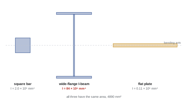
The comparison is striking. The I-beam and a solid square bar contain the same amount of steel, yet the I-beam's second moment is about 42 times larger, because most of its area is in flanges 150 mm from the centroid, while the bar's material is clustered around it. The web holds the flanges apart and carries most of the shear (Lesson 8); the flanges do most of the work in bending.
Why the second moment matters
Mechanics of materials, the course that follows statics, uses the second moment in nearly every formula. Three results show why it matters so much:
- Bending stress. In a beam carrying bending moment M, the normal stress at distance y from the neutral axis, which passes through the centroid (Lesson 6), is \(\sigma = My/I\). The largest stress is at the extreme fibre, distance c from the axis, so \(\sigma_{\max} = Mc/I = M/S\), where \(S = I/c\) is the section modulus. Steel section tables list S for every shape.
- Deflection. A beam's deflection is inversely proportional to EI, the product of the material's stiffness (modulus of elasticity E) and the second moment. A simply supported beam with a uniform load deflects \(5wL^4/(384EI)\) at midspan.
- Buckling. A slender column buckles sideways at the Euler load \(P_{cr} = \pi^2EI/L^2\) (for pinned ends), and it buckles about the axis with the smaller I. This is why the compression members of Lesson 5's trusses are made from shapes with large I in every direction, such as tubes and wide-flange sections.
Worked problem
Bending stress in the floor beam
The office floor beam of Lessons 7 and 8 has a service bending moment of 142 kN·m. If it is the wide-flange section in the code output (depth 310 mm, I = 84.1 × 10⁶ mm⁴), what is the maximum bending stress?
Show solution
- Extreme fibre distance: c = 310/2 = 155 mm.
- \(\sigma_{\max} = Mc/I = 142 \times 10^6 \times 155/(84.1 \times 10^6) = 262\) MPa.
Answer: 262 MPa at service load, compression in the top flange and tension in the bottom. Structural steel commonly has a yield strength of 345 to 350 MPa, so this section would be too highly stressed once load factors and resistance factors are applied; the designer would choose a deeper, heavier section with a larger section modulus, and also check deflection and lateral buckling of the compression flange. These checks are the subject of steel design courses, but they all rest on the section properties found here.
Worked problem
A tube versus a solid rod as a column
A 3.0 m pin-ended steel strut (E = 200 GPa) is made either from a solid 50 mm diameter rod or from a tube of the same cross-sectional area with a 100 mm outside diameter. Compare their Euler buckling loads.
Show solution
- Rod: \(I = \pi(25)^4/4 = 0.307 \times 10^6\) mm⁴. \(P_{cr} = \pi^2(200\,000)(0.307 \times 10^6)/3000^2 = 67\) kN.
- Tube: area \(\pi(25)^2 = 1963\) mm² requires \(r_i^2 = 50^2 - 25^2\), so \(r_i = 43.3\) mm. \(I = \pi(50^4 - 43.3^4)/4 = 2.15 \times 10^6\) mm⁴. \(P_{cr} = 471\) kN.
Answer: The tube carries about seven times the buckling load of the solid rod with exactly the same amount of steel. That is why bicycle frames, scaffolding, truss compression members and columns use hollow sections. The limit is local buckling: if the walls become too thin, they crumple locally, so design codes limit the diameter-to-thickness ratio.
Centre of pressure revisited
Lesson 7 found the force of water on a submerged plane surface, \(F = \rho g h_c A\), and noted that it acts below the centroid. The second moment gives the location directly. For a vertical surface whose centroid is at depth \(h_c\), the centre of pressure is at depth:
For Lesson 7's gate, 1.0 m wide and 1.5 m high with its centroid 2.75 m deep: \(\bar{I} = 1.0 \times 1.5^3/12 = 0.281\) m⁴, so \(h_p = 2.75 + 0.281/(2.75 \times 1.5) = 2.82\) m, matching the trapezoid calculation. The formula works for any shape: circular inspection hatches, triangular gates and inclined panels (using distances measured along the incline).
Principal axes
For unsymmetric shapes such as angles (L-sections) and Z-sections, the second moment changes with the orientation of the axis, and a third property, the product of inertia \(I_{xy} = \int xy\,dA\), is needed. There is always one pair of perpendicular axes through the centroid, the principal axes, about which I takes its maximum and minimum values and the product of inertia is zero; for any shape with an axis of symmetry, that axis is a principal axis. A single angle loaded vertically bends about its principal axes, not about its legs, so it deflects sideways as well as down, a behaviour engineers must account for when angles are used as lintels or bracing. Steel tables list the principal second moments and the least radius of gyration of every angle, because a slender angle in compression buckles about its weakest axis.
Common mistakes
MistakeUsing bh³/12 with b and h swapped.
Insteadh is the dimension perpendicular to the bending axis; it is cubed.
MistakeAdding parts' own second moments without the Ad² terms.
InsteadUse the parallel-axis theorem about the composite centroid.
MistakeTaking distances d from the bottom of the section.
InsteadMeasure d from the composite centroid.
MistakeChecking column buckling about the stronger axis.
InsteadColumns buckle about the axis with the smaller I.
MistakeConfusing area and mass moments of inertia.
InsteadArea moments (mm⁴) govern bending; mass moments (kg·m²) govern rotation.
Summary and key terms
- The second moment I = ∫y² dA measures how area is spread from an axis; units are length⁴.
- Rectangle: bh³/12; circle: πr⁴/4; polar moment J = I_x + I_y.
- Parallel-axis theorem: I = Ī + Ad²; the centroidal axis gives the minimum.
- Composite sections: sum each part's Ī + Ad² about the composite centroid.
- Moving material away from the centroid, as in I-beams and tubes, greatly increases I.
- Bending stress σ = My/I, deflection ∝ 1/(EI), buckling load ∝ EI.
- The centre of pressure lies Ī/(h_c A) below the centroid; unsymmetric shapes need principal axes.
- Second moment of area
- The integral of distance squared times area about an axis.
- Polar moment of inertia
- The second moment about an axis perpendicular to the area, J = I_x + I_y.
- Radius of gyration
- k = √(I/A), the distance giving the same second moment if all area were there.
- Parallel-axis theorem
- I = Ī + Ad², relating second moments about parallel axes.
- Neutral axis
- The line in a bent beam with zero bending stress, through the centroid.
- Section modulus
- S = I/c; maximum bending stress equals M/S.
- Flexural rigidity
- EI, a beam's resistance to bending deflection.
- Euler buckling load
- The critical compressive load π²EI/L² of a pin-ended column.
- Product of inertia
- I_xy = ∫xy dA, zero about principal axes.
- Principal axes
- Axes about which the second moment is maximum and minimum.
Practice problems
Work each problem on paper first, then reveal the answer to check.
Find I for a 100 × 300 mm rectangle about its strong axis (300 mm vertical).
Show answer
100 × 300³/12 = 225 × 10⁶ mm⁴.
Find I for the same rectangle about its weak axis.
Show answer
300 × 100³/12 = 25 × 10⁶ mm⁴.
Find I for a solid 40 mm diameter shaft about a diameter, and its polar moment.
Show answer
π(20)⁴/4 = 0.126 × 10⁶ mm⁴; J = 0.251 × 10⁶ mm⁴.
A 100 × 20 mm plate has its centroid 150 mm from an axis. Find its I about that axis (strong direction horizontal).
Show answer
100 × 20³/12 + 2000 × 150² = 0.067 + 45.0 = 45.1 × 10⁶ mm⁴.
From the code output, what is the section modulus at the bottom of the T-section?
Show answer
About 202 × 10³ mm³.
A section has S = 500 × 10³ mm³. What moment gives a stress of 250 MPa?
Show answer
125 kN·m.
By what factor does doubling a rectangular beam's depth reduce its deflection?
Show answer
Eight (I grows as h³).
Find the radius of gyration of a 50 mm solid rod.
Show answer
√(I/A) = r/2 = 12.5 mm.
Find the Euler load of a 2.0 m pin-ended column with I = 1.0 × 10⁶ mm⁴ and E = 200 GPa.
Show answer
π² × 200 000 × 10⁶/2000² = 493 kN.
A vertical circular hatch of radius 0.3 m has its centre 4.0 m below the surface. How far below the centre does the water force act?
Show answer
Ī/(h_c A) = (π0.3⁴/4)/(4.0 × π0.3²) = 0.0056 m.
Lesson quiz · 5 questions
Score 60% or more to complete this lesson.
Create a free account to save your progress, take quizzes and earn a certificate.