
MEC-230 · Lesson 7 of 12 · 26 min
Mass and energy analysis of control volumes
Almost nothing at Northgate is a closed system. Steam flows through the turbine, water through the pumps, flue gas through the stack, air through the compressor. To analyze these devices we draw a control volume around each and keep track of the mass and energy crossing its surface. The laws are the same as for closed systems: mass is conserved and energy is conserved. What changes is the bookkeeping, because mass entering and leaving carries energy with it, and pushing that mass across the boundary takes work. This lesson develops the mass and energy balances for control volumes and specializes them to steady flow, the condition in which the plant spends almost all its time.
Conservation of mass
For a closed system, mass conservation is automatic: the mass is fixed by definition. For a control volume, the principle reads: the net mass transferred into the control volume during a time interval equals the change in the mass inside it.
The mass flow rate \(\dot{m}\) through a cross-section of area \(A\), where the fluid has density \(\rho\) and mean velocity \(V\) normal to the section, is \(\dot{m} = \rho V A = VA/v\). The volume flow rate is \(\dot{V} = VA = \dot{m}v\). In a pipe the velocity varies across the section, from zero at the wall to a maximum on the centreline; \(V\) here is the average velocity, defined so that \(\rho VA\) gives the correct mass flow.
In steady flow, nothing inside the control volume changes with time, so its mass is constant and \(dm_{CV}/dt = 0\). The total mass flow in then equals the total mass flow out. For a single stream, \(\dot{m}_1 = \dot{m}_2\), or \(\rho_1V_1A_1 = \rho_2V_2A_2\). Note that it is mass, not volume, that is conserved: when steam expands through a turbine its density falls, so its volume flow rate rises even though its mass flow rate is unchanged. Only for incompressible liquids are volume flows conserved too.
Worked problem
Velocities in the plant piping
At full load, 12 kg/s of steam flows from the boilers. Find the mean velocity (a) in the 250 mm bore header at 4 MPa and 400 °C, where \(v = 0.07343\ \text{m}^3/\text{kg}\); (b) in the 400 mm bore district main at 1 MPa and 250 °C, where \(v = 0.23275\); (c) in the 150 mm condensate return at 85 °C, where \(v = 0.001032\).
Show solution
- (a) \(A = \pi(0.250)^2/4 = 0.04909\ \text{m}^2\); \(V = \dot{m}v/A = 12(0.07343)/0.04909 = 17.9\ \text{m/s}\).
- (b) \(A = 0.1257\ \text{m}^2\); \(V = 12(0.23275)/0.1257 = 22.2\ \text{m/s}\).
- (c) \(A = 0.01767\ \text{m}^2\); \(V = 12(0.001032)/0.01767 = 0.70\ \text{m/s}\).
Answer: The same 12 kg/s needs a pipe of about 0.13 m² as low-pressure steam and moves at a walking pace as liquid in a pipe one-seventh the area. Steam velocities of 20 to 40 m/s are normal design values; higher velocities cause noise and erosion, especially with wet steam. Condensate lines are sized for low velocities to avoid water hammer and to leave room for flash steam.
Flow work
Unlike a closed system, a control volume has mass crossing its boundary, and that takes work. Imagine a small slug of fluid of volume \(V\) about to enter the control volume. The fluid behind it, at pressure \(P\), pushes it in, acting with force \(PA\) through the distance \(L = V/A\). The work done is \(PA \times V/A = PV\), or per unit mass, \(Pv\). This flow work, or flow energy, is energy transferred into the control volume with each kilogram entering; similarly, the fluid in the control volume does flow work \(Pv\) per kilogram to push fluid out at each exit.
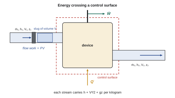
Flow work is sometimes listed as a form of energy of the flowing fluid and sometimes as a work interaction. The second view is more physical, but the first is more convenient, and the bookkeeping comes out the same either way. With flow work counted as part of the energy of the stream, each kilogram of flowing fluid carries
This is where enthalpy earns its keep. The combination \(u + Pv\) appears automatically for every stream crossing the boundary, and having a single tabulated property for it simplifies every control-volume analysis. The energy carried by a stream per unit time is \(\dot{m}\theta = \dot{m}(h + V^2/2 + gz)\).
The energy balance for a control volume
For a control volume, energy crosses the boundary as heat, as work (shaft, electrical, boundary if the control volume deforms), and with mass. Excluding flow work from the work term, since it is now inside \(\theta\), the general energy balance in rate form is
This one equation covers turbines, compressors, boilers, tanks being filled, and everything else. It is easier to apply in two special forms. The first, steady flow, is the subject of the rest of this lesson and the next. The second, uniform flow for devices whose contents change over time, such as a tank being filled, is the subject of Lesson 9.
Steady-flow processes
In steady flow, no property at any point in the control volume changes with time, so its mass and energy content are constant: \(dm_{CV}/dt = 0\) and \(dE_{CV}/dt = 0\). The heat transfer and power are also steady. The balances become
For a device with one inlet (state 1) and one outlet (state 2), the mass flow is the same at both, and dividing by \(\dot{m}\) gives the steady-flow energy equation per unit mass:
Here \(q = \dot{Q}/\dot{m}\) and \(w = \dot{W}/\dot{m}\) are heat and work per kilogram of fluid flowing through. Mind the units: \(h\) is in kJ/kg, while \(V^2/2\) and \(gz\) come out in J/kg and must be divided by 1000.
Which terms matter?
In most devices some terms in the steady-flow energy equation are negligible, and recognizing which ones is half the skill. Kinetic energy changes are small unless velocities are large: a change from 2 m/s to 30 m/s is only 0.45 kJ/kg. They matter in nozzles and diffusers, whose whole purpose is to change velocity, and occasionally at turbine exhausts. Potential energy changes are almost always negligible in thermal devices, at about 0.1 kJ/kg per 10 m of elevation; they matter for water pumped up tall buildings or through hydroelectric plants. Heat transfer is negligible in well-insulated devices and in those where the fluid passes through too quickly to exchange much heat, such as turbines and compressors. Work is zero in devices with no shafts, wires or moving boundaries, such as heat exchangers, valves, nozzles and pipes.
The program below makes this concrete for the steam that heats a building 40 m above the plant. It compares the enthalpy change between steam in the main and condensate leaving the building with the changes in kinetic and potential energy, and finds the steam flow a building needs for a given heat load.
# Mass flow, velocity and the size of each energy term for flows in the plant
import math

def velocity(mdot, v, D):
    """Mean velocity (m/s) for mass flow mdot (kg/s), specific volume v (m3/kg), pipe bore D (m)."""
    A = math.pi * D**2 / 4
    return mdot * v / A

flows = [   # name, mdot kg/s, v m3/kg, bore m
    ("steam main, 1 MPa 250 C", 12.0, 0.23275, 0.400),
    ("condensate return, 85 C",  12.0, 0.001032, 0.150),
    ("boiler outlet, 4 MPa 400 C", 12.0, 0.07343, 0.250),
]
print(f"{'flow':28s} {'V m/s':>7s} {'Vol m3/s':>9s} {'KE kJ/kg':>9s}")
for name, mdot, v, D in flows:
    V = velocity(mdot, v, D)
    print(f"{name:28s} {V:7.2f} {mdot * v:9.4f} {V**2 / 2 / 1000:9.3f}")

# Compare the energy terms for steam delivered to a building 40 m higher than the plant
dh = 2943.1 - 356.0             # kJ/kg released when steam at 1 MPa 250 C returns as 85 C condensate
dke = (30.0**2 - 2.0**2) / 2 / 1000
dpe = 9.81 * 40 / 1000
print(f"\nenthalpy change {dh:8.1f} kJ/kg")
print(f"kinetic energy  {dke:8.3f} kJ/kg ({100 * dke / dh:.3f} % of dh)")
print(f"potential energy{dpe:8.3f} kJ/kg ({100 * dpe / dh:.3f} % of dh)")

# Steam needed by a building that requires 1.8 MW of heat
Q = 1800.0
print(f"\nsteam for 1.8 MW: {Q / dh:.3f} kg/s = {Q / dh * 3600:.0f} kg/h")flow V m/s Vol m3/s KE kJ/kg steam main, 1 MPa 250 C 22.23 2.7930 0.247 condensate return, 85 C 0.70 0.0124 0.000 boiler outlet, 4 MPa 400 C 17.95 0.8812 0.161 enthalpy change 2587.1 kJ/kg kinetic energy 0.448 kJ/kg (0.017 % of dh) potential energy 0.392 kJ/kg (0.015 % of dh) steam for 1.8 MW: 0.696 kg/s = 2505 kg/h
The kinetic and potential energy terms are each less than 0.02 percent of the enthalpy change. For steam heating, enthalpy is everything. The same conclusion holds for most heat exchangers, boilers, condensers and pipes: the energy balance reduces to \(\dot{Q} = \dot{m}(h_2 - h_1)\) for each stream.
Worked problem
Steam demand of the hospital
The hospital's heat exchanger condenses steam from the main at 1 MPa and 250 °C and returns condensate at 85 °C. On a −30 °C January morning the hospital needs 1.8 MW for space heating and domestic hot water. What steam flow must the plant deliver to it? Take \(h_1 = 2943.1\) and \(h_2 \approx h_f(85\ °\text{C}) = 356.0\ \text{kJ/kg}\).
Show solution
- Control volume: the steam side of the heat exchanger. Steady flow, no work, negligible \(\Delta KE\) and \(\Delta PE\). Heat leaves the steam.
- \[-\dot{Q}_{\text{out}} = \dot{m}(h_2 - h_1) \quad\Rightarrow\quad \dot{m} = \frac{1800}{2943.1 - 356.0} = 0.696\ \text{kg/s}\]
Answer: About 2,500 kg/h, or 5.8 percent of the plant's full-load steam. Each kilogram gives up 2,587 kJ, of which about 2,000 kJ is latent heat released by condensation and the rest comes from cooling the superheated steam and then the condensate. If the condensate left at a higher temperature, say 120 °C, each kilogram would release less and the steam flow would have to rise.
Energy balances on the whole plant
Control volumes can be drawn around a single component or around a whole system. Drawing one around the entire boiler house, with natural gas and air entering, flue gas leaving, feedwater entering and steam leaving, gives the boiler efficiency directly. Drawing one around the whole district loop, including the plant and every building, shows that in steady operation the fuel energy entering must equal the heat delivered to buildings plus all the losses: up the stacks, through pipe insulation, in the cooling tower, and as electricity exported from the turbine generator. Northgate's annual energy report is exactly such a balance, and the losses it reveals guide where the plant spends its maintenance budget.
Worked problem
Heat lost from the buried steam main
Measurements one winter week found that steam entering a 1.2 km run of buried main at 1 MPa and 250 °C left at 1 MPa and 238 °C, with a steady flow of 9.0 kg/s. The steam table gives \(h = 2943.1\ \text{kJ/kg}\) at 250 °C and, by interpolation, about 2915.5 kJ/kg at 238 °C. Estimate the heat loss.
Show solution
- Control volume: the steam inside the pipe run. Steady flow, no work, negligible \(\Delta KE\) and \(\Delta PE\) (the pipe is nearly level and velocity barely changes).
- \[\dot{Q}_{\text{out}} = \dot{m}(h_1 - h_2) = 9.0(2943.1 - 2915.5) = 248\ \text{kW}\]
Answer: About 250 kW, or roughly 200 W per metre of pipe. Over a heating season that is several thousand megawatt-hours. The measurement also hides a subtlety: the pressure actually drops a little along the pipe because of friction, so a careful analysis would use the measured outlet pressure. Losses like this are a large part of the argument for converting to lower-temperature hot water.
Common mistakes
MistakeAssuming volume flow is conserved for a gas or vapour.
InsteadMass flow is conserved; volume flow changes as density changes.
MistakeUsing u instead of h for the energy of a flowing stream.
InsteadFlowing fluid carries h + V²/2 + gz, which includes the flow work Pv.
MistakeAdding V²/2 in m²/s² to h in kJ/kg.
InsteadDivide kinetic and potential terms by 1000 to get kJ/kg.
MistakeIncluding flow work again in the work term.
InsteadFlow work is already inside h; Ẇ includes only shaft, electrical and boundary work.
MistakeKeeping every term in the steady-flow equation.
InsteadDecide which terms are negligible for the device and cancel them explicitly.
Summary and key terms
- Mass balance: Σṁ_in − Σṁ_out = dm_CV/dt; in steady flow, mass in equals mass out.
- ṁ = ρVA = VA/v; volume flow V̇ = ṁv is not conserved for compressible fluids.
- Flow work Pv is needed to push fluid across a boundary; with u it forms h.
- A flowing stream carries θ = h + V²/2 + gz per unit mass.
- Steady flow: Q̇ − Ẇ = Σṁ_out θ_out − Σṁ_in θ_in.
- Single stream: q − w = Δh + ΔV²/2 + gΔz.
- Kinetic and potential energy changes are usually negligible except in nozzles, diffusers and hydraulic systems.
- Control volume
- A region in space chosen for analysis, through whose surface mass may flow.
- Mass flow rate
- The mass passing through a cross-section per unit time, ṁ = ρVA.
- Volume flow rate
- The volume passing through a cross-section per unit time, V̇ = VA.
- Conservation of mass
- Mass cannot be created or destroyed; for a control volume, net inflow equals accumulation.
- Flow work
- The work Pv per unit mass needed to push fluid into or out of a control volume.
- Steady-flow process
- A process in which properties at every point in a control volume are constant in time.
- Steady-flow energy equation
- q − w = Δh + ΔV²/2 + gΔz for a single-stream steady-flow device.
Practice problems
Work each problem on paper first, then reveal the answer to check.
Air at 200 kPa and 30 °C flows at 8 m/s in a 0.3 m diameter duct. Find the mass flow rate.
Show answer
1.30 kg/s.
Steam at 0.4 MPa with v = 0.53434 m³/kg flows at 5 kg/s and 30 m/s. What pipe diameter is needed?
Show answer
About 0.336 m.
Water enters a 100 m tall building's riser at 2 m/s and leaves at the top at 2 m/s. Find Δpe in kJ/kg.
Show answer
0.981 kJ/kg.
Steam at 1 MPa and 300 °C (h = 3051.6) is condensed to liquid at 90 °C (h ≈ 377.0). Find the heat released per kilogram.
Show answer
2674.6 kJ/kg.
A building needs 950 kW. Using the hospital's steam and condensate states, what steam flow does it need?
Show answer
0.367 kg/s, about 1,320 kg/h.
In the program, what pipe bore keeps the boiler-outlet steam at 25 m/s?
Show answer
About 0.212 m.
Lesson quiz · 5 questions
Score 60% or more to complete this lesson.
Create a free account to save your progress, take quizzes and earn a certificate.