
ROB-110 · Lesson 10 of 12 · 29 min
Coordinate frames and transforms with tf2
A laser scanner reports that an obstacle is 1 m away, straight ahead. Straight ahead of what? Of the scanner, which may be mounted at the front of the robot, at the back or upside down, and the robot itself is somewhere in a room, facing some direction. Before the robot can avoid the obstacle, put it on a map or tell an arm to reach for it, the measurement must be expressed in the right coordinate frame. Every robot juggles many frames: one for each sensor, one for the body, one for the world, and, for an arm, one for every link. ROS 2's tf2 library keeps track of how all these frames are related as they move, and converts data between them on request. This lesson explains the standard frames, the mathematics of transforms in two dimensions, quaternions for orientation and how to publish and use transforms with tf2.
The standard frames of a mobile robot
ROS conventions, recorded in REP 105, name the main frames of a mobile robot. base_link is rigidly attached to the robot's body, usually at the centre of rotation, with x forward, y left and z up. Each sensor has its own frame, such as laser or camera_link, fixed relative to base_link by how it is mounted. odom is a world-fixed frame in which the robot's pose is estimated by odometry: it changes smoothly and continuously, which suits short-term control, but it drifts over time as wheel slip errors accumulate. map is a world-fixed frame in which a localization system estimates the robot's pose against a map: it does not drift, but the estimate can jump when the localizer corrects itself. The frames form a tree: map is the parent of odom, odom the parent of base_link, and base_link the parent of each sensor frame.
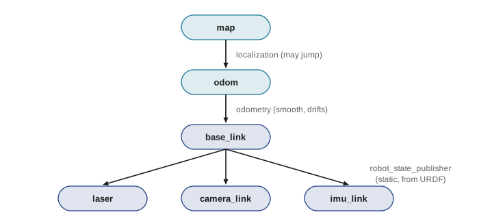
Why have both odom and map? Because the two estimates serve different purposes and are produced by different nodes. A controller following a path needs a pose that changes smoothly, which odom provides. A planner needs to know where the robot is in the building, which map provides. Rather than having the localizer publish the robot's pose directly, it publishes the correction between map and odom, so that the chain map to odom to base_link gives the best estimate of the robot in the map while odom to base_link stays smooth. Each frame has exactly one parent, and each transform is published by exactly one node; publishing the same transform from two nodes, or giving a frame two parents, breaks the tree.
Transforms in two dimensions
A transform from a child frame to a parent frame says where the child is in the parent: a translation \( (t_x, t_y) \) and a rotation by an angle θ. A point with coordinates \( (x_c, y_c) \) in the child frame has these coordinates in the parent frame:
Rotating then translating is awkward to chain, so robotics uses homogeneous coordinates: a 2-D point is written with an extra 1 as (x, y, 1), and a transform becomes a single 3 × 3 matrix that rotates and translates in one multiplication. The great advantage is that transforms compose by matrix multiplication. If you know the laser in base_link, base_link in odom and odom in map, the laser in map is their product, multiplied in order from the top of the tree down:
The inverse matrix gives the transform in the opposite direction, from parent to child. The program below builds the three transforms for a robot with a backwards-mounted laser, composes them and converts an obstacle detected 1 m in front of the laser into base_link and map coordinates, then inverts the chain to recover the original point.
import numpy as np


def T(x, y, yaw_deg):
    """2-D homogeneous transform: rotate by yaw, then translate."""
    c, s = np.cos(np.radians(yaw_deg)), np.sin(np.radians(yaw_deg))
    return np.array([[c, -s, x],
                     [s,  c, y],
                     [0,  0, 1]])


# parent <- child transforms
map_odom = T(0.5, -0.2, 5)       # localization correction
odom_base = T(3.0, 1.0, 90)      # robot pose from odometry
base_laser = T(0.2, 0.0, 180)    # laser mounted backwards

p_laser = np.array([1.0, 0.0, 1])           # obstacle seen by laser
map_laser = map_odom @ odom_base @ base_laser
p_map = map_laser @ p_laser
print("in base_link:", np.round((base_laser @ p_laser)[:2], 3))
print("in map:      ", np.round(p_map[:2], 3))

# the inverse takes map coordinates back to the laser frame
back = np.linalg.inv(map_laser) @ p_map
print("back in laser:", np.round(back[:2], 3))in base_link: [-0.8 0. ] in map: [3.471 0.261] back in laser: [1. 0.]
Worked problem
Following the point through the tree
Verify the program's first step and the point in odom. The laser is mounted 0.2 m ahead of base_link and rotated 180°; the robot is at (3.0, 1.0) in odom facing 90°. An obstacle is 1 m straight ahead of the laser.
Show solution
- In the laser frame the point is (1, 0).
- Rotating by 180° gives (−1, 0); adding the mounting offset (0.2, 0) gives (−0.8, 0) in base_link: 0.8 m behind the robot.
- Rotating (−0.8, 0) by 90° gives (0, −0.8); adding the robot position (3.0, 1.0) gives (3.0, 0.2) in odom.
- The map to odom correction (0.5, −0.2) and 5° then moves it to about (3.47, 0.26) in map, as printed.
Answer: The obstacle is at (−0.8, 0) in base_link, (3.0, 0.2) in odom and about (3.47, 0.26) in map.
Order matters. Matrix multiplication is not commutative, so multiplying the transforms in the wrong order gives a wrong answer that may look plausible. The rule is to chain from the frame you want the answer in down to the frame the data is in, with each child frame of one transform matching the parent frame of the next. Writing the frames as superscripts and subscripts, as in the equation above, makes mismatches easy to spot.
Orientation in three dimensions: quaternions
Real robots live in three dimensions. Positions are simply (x, y, z), but orientations are harder. Three angles, roll, pitch and yaw, are intuitive, but they suffer from gimbal lock, a configuration in which two of the angles describe the same motion and the representation breaks down, and they are awkward to combine. ROS 2 therefore represents orientation with quaternions, sets of four numbers (x, y, z, w) whose squares add up to 1. Quaternions combine smoothly, never lock and are cheap to compute with, at the cost of being hard to read. For a ground robot that only turns about its vertical axis, the quaternion has a simple form: x and y are zero, z is the sine of half the yaw angle and w is its cosine.
import math


def yaw_to_quaternion(yaw):
    """Quaternion (x, y, z, w) for a rotation about z only."""
    return (0.0, 0.0, math.sin(yaw / 2), math.cos(yaw / 2))


def quaternion_to_yaw(x, y, z, w):
    return math.atan2(2 * (w * z + x * y), 1 - 2 * (y * y + z * z))


for deg in [0, 90, 180, -45]:
    q = yaw_to_quaternion(math.radians(deg))
    back = math.degrees(quaternion_to_yaw(*q))
    print(f"yaw {deg:4d} deg -> q = ({q[0]:.0f}, {q[1]:.0f}, "
f"{q[2]:.3f}, {q[3]:.3f}) -> {back:.0f} deg")yaw 0 deg -> q = (0, 0, 0.000, 1.000) -> 0 deg yaw 90 deg -> q = (0, 0, 0.707, 0.707) -> 90 deg yaw 180 deg -> q = (0, 0, 1.000, 0.000) -> 180 deg yaw -45 deg -> q = (0, 0, -0.383, 0.924) -> -45 deg
Note that a robot facing straight ahead has quaternion (0, 0, 0, 1), not all zeros: a quaternion of all zeros is invalid, and a message left with its default zero orientation is a common source of errors and warnings. For general 3-D rotations, use a library rather than writing conversions yourself: the transforms3d and scipy packages in Python, and tf2's own helpers, convert between quaternions, rotation matrices and roll, pitch and yaw. ROB-210 develops 3-D transforms fully with 4 × 4 homogeneous matrices.
Static and dynamic transforms in tf2
tf2 distinguishes two kinds of transform. Static transforms never change, such as the mounting of a laser on the robot body. They are published once on the /tf_static topic with transient-local durability, so late-joining nodes still receive them. Dynamic transforms change over time, such as odom to base_link as the robot drives, and are published repeatedly, with timestamps, on /tf. Every node that uses transforms keeps a buffer of recent transforms, typically the last ten seconds, so that it can look up where frames were at any moment in that window.
For a quick static transform you do not need to write code. The static_transform_publisher program publishes one from command-line arguments, and tf2_echo prints the transform between any two frames as it changes. On a real robot, the static transforms usually come from the robot's description, a URDF file listing its links and joints, which a node called robot_state_publisher turns into transforms.
# laser 0.2 m ahead and 0.15 m above base_link, facing backwards
ros2 run tf2_ros static_transform_publisher --x 0.2 --z 0.15 \
  --yaw 3.14159 --frame-id base_link --child-frame-id laser
# print a transform as it changes
ros2 run tf2_ros tf2_echo odom laser
# draw the whole tree to frames.pdf
ros2 run tf2_tools view_frames
Dynamic transforms are published from code with a TransformBroadcaster. A node that estimates odometry publishes odom to base_link each time it updates. The listing below shows the essential steps: fill a TransformStamped message with the timestamp, parent and child frame names, translation and rotation, then send it.
from geometry_msgs.msg import TransformStamped
from nav_msgs.msg import Odometry
from tf2_ros import TransformBroadcaster


class OdomTf(Node):
    def __init__(self):
        super().__init__('odom_tf')
        self.br = TransformBroadcaster(self)
        self.create_subscription(Odometry, 'odom', self.on_odom, 10)

    def on_odom(self, msg):
        t = TransformStamped()
        t.header.stamp = msg.header.stamp      # keep the data's time
        t.header.frame_id = 'odom'             # parent
        t.child_frame_id = 'base_link'         # child
        t.transform.translation.x = msg.pose.pose.position.x
        t.transform.translation.y = msg.pose.pose.position.y
        t.transform.rotation = msg.pose.pose.orientation
        self.br.sendTransform(t)
To use transforms, a node creates a Buffer and a TransformListener, which subscribes to /tf and /tf_static and fills the buffer. lookup_transform then returns the transform between any two frames in the tree, composing the chain automatically, exactly as the NumPy program did by hand. Passing Time(), a zero time, asks for the latest available transform. Lookups can fail, for example at start-up before transforms have arrived or when a frame name is misspelled, so always handle TransformException.
from rclpy.time import Time
from tf2_ros import Buffer, TransformListener, TransformException


class Watcher(Node):
    def __init__(self):
        super().__init__('watcher')
        self.buffer = Buffer()
        self.listener = TransformListener(self.buffer, self)
        self.create_timer(0.5, self.on_timer)

    def on_timer(self):
        try:
            t = self.buffer.lookup_transform('odom', 'laser', Time())
        except TransformException as ex:
            self.get_logger().warning(f'no transform yet: {ex}')
            return
        p = t.transform.translation
        self.get_logger().info(f'laser at x={p.x:.2f}, y={p.y:.2f}')
To transform data such as points, poses and vectors rather than just reading a transform, the tf2_geometry_msgs package provides helpers that apply a looked-up transform to a stamped message. Time matters here: a laser scan taken 80 ms ago should be transformed using where the robot was 80 ms ago, not where it is now. Looking up the transform at the scan's own timestamp does exactly that, which is why sensor messages carry timestamps and why clocks must be synchronized across computers, as lesson 2 warned.
Worked problem
The cost of using the wrong time
A robot turns on the spot at 1.5 rad/s. A scan point 4 m away is transformed into odom using the latest transform instead of the transform at the scan's timestamp, which was 80 ms earlier. Roughly how far out of place does the point land?
Show solution
- Heading change in 80 ms: \( 1.5 \times 0.08 = 0.12 \) rad, about 6.9°.
- A point 4 m away moves sideways by about \( 4 \times 0.12 = 0.48 \) m.
Answer: About half a metre. Obstacles would appear smeared or in the wrong place, which is why transforms are looked up at the data's timestamp.
Common mistakes
MistakeMultiplying transforms in the wrong order.
InsteadChain from the target frame down to the data's frame, checking that each child matches the next parent.
MistakeLeaving a quaternion at all zeros.
InsteadThe identity orientation is (0, 0, 0, 1); always set orientation explicitly.
MistakePublishing the same transform from two nodes or giving a frame two parents.
InsteadKeep a single tree with one publisher per transform.
MistakeUsing the latest transform for old sensor data on a moving robot.
InsteadLook up transforms at the data's timestamp and keep clocks synchronized.
MistakeIgnoring TransformException at start-up.
InsteadCatch it, log it and try again later; transforms arrive a moment after nodes start.
Summary and key terms
- Robots use many coordinate frames; REP 105 defines map, odom, base_link and sensor frames arranged in a tree.
- odom is smooth but drifts; map does not drift but can jump; localization publishes the map to odom correction.
- A 2-D transform is a rotation and translation, written as a 3 × 3 homogeneous matrix; transforms compose by multiplication in order and invert with the matrix inverse.
- Orientation in ROS 2 is a quaternion (x, y, z, w); for yaw only, z = sin(yaw/2) and w = cos(yaw/2).
- Static transforms go on /tf_static once; dynamic transforms go on /tf with timestamps.
- TransformBroadcaster publishes transforms; Buffer and TransformListener look them up, composing chains automatically.
- Look up transforms at the data's timestamp; using the wrong time on a turning robot misplaces data noticeably.
- Coordinate frame
- A reference system of origin and axes in which positions and orientations are expressed.
- base_link
- The frame rigidly attached to the robot's body.
- odom frame
- A world-fixed frame in which odometry gives a smooth but drifting pose.
- map frame
- A world-fixed frame in which localization gives a drift-free pose that may jump.
- Transform
- The translation and rotation relating a child frame to its parent.
- Homogeneous coordinates
- Coordinates with an extra 1 that let rotation and translation be combined in one matrix.
- Quaternion
- A four-number representation of 3-D orientation without gimbal lock.
- Static transform
- A transform that never changes, published on /tf_static.
- tf2 buffer
- A store of recent transforms that answers lookups between any two frames.
- URDF
- An XML description of a robot's links and joints, used to publish its fixed transforms.
Practice problems
Work each problem on paper first, then reveal the answer to check.
Which frame would you use to plan a path across a building, and which for a smooth short-term controller?
Show answer
map for planning; odom for the controller.
A camera is mounted 0.3 m ahead of base_link with no rotation. A point is at (2, 0) in the camera frame. Where is it in base_link?
Show answer
(2.3, 0).
The robot is at (1, 2) in odom facing 180°. A point is at (1, 0) in base_link. Where is it in odom?
Show answer
Rotating (1, 0) by 180° gives (−1, 0); adding (1, 2) gives (0, 2).
Write the quaternion for a yaw of 60°.
Show answer
(0, 0, sin 30°, cos 30°) = (0, 0, 0.5, 0.866).
Why does the localization node publish map to odom rather than map to base_link?
Show answer
So that odom to base_link stays smooth and each frame keeps one parent; the chain gives the robot's pose in map.
Which topic carries the laser's mounting transform, and with what durability?
Show answer
/tf_static, with transient-local durability.
What does passing Time() to lookup_transform request?
Show answer
The latest available transform.
A robot turns at 0.8 rad/s and a scan 100 ms old is transformed with the latest transform. How far off is a point 5 m away?
Show answer
0.08 rad × 5 m ≈ 0.4 m.
Write the composition for the camera in map, given map to odom, odom to base_link and base_link to camera.
Show answer
T(map, camera) = T(map, odom) T(odom, base_link) T(base_link, camera).
What command draws the current transform tree?
Show answer
ros2 run tf2_tools view_frames
Lesson quiz · 5 questions
Score 60% or more to complete this lesson.
Create a free account to save your progress, take quizzes and earn a certificate.