
ROB-320 · Lesson 10 of 12 · 33 min
Real-time communication, middleware and time synchronization
A robot is a distributed computer. Its joint drives, force sensors, IMUs, cameras, safety controller and main computer are separate processors joined by buses and networks, and a control loop often spans several of them: the encoder reading travels to the controller, the command travels to the drive. The network is therefore part of every latency budget, and its worst case matters as much as any task's. This lesson covers the timing of the networks robots use, from CAN to EtherCAT and time-sensitive Ethernet, the quality-of-service settings that make DDS and ROS 2 middleware behave predictably, and how clocks on separate devices are synchronized so that measurements taken in different places can be combined. ROB-200 described the physical and electrical side of UART, I2C, SPI and CAN; this lesson treats networks as schedulable resources.
What makes a network real-time
A real-time network bounds the time from when a message is ready to send until it is delivered, for every message, even when the network is busy. Ordinary Ethernet with TCP/IP does not: switches queue frames, collisions and congestion cause variable delays, and TCP retransmits lost data after timeouts measured in hundreds of milliseconds. Real-time networks achieve bounded delay in one of three ways: by priority arbitration (CAN), by a master that schedules all traffic in fixed cycles (EtherCAT, PROFINET IRT, many fieldbuses), or by time-aware scheduling of switch queues (time-sensitive networking, TSN).
CAN timing
CAN arbitrates by message identifier: when several nodes start sending at once, the lowest identifier wins without being delayed and the others back off and retry. CAN is therefore a fixed-priority, non-preemptive scheduler for messages, and the response-time analysis of lesson 5 applies to it, with one twist: a frame already being transmitted cannot be interrupted, so a high-priority message can be blocked for up to one maximum-length frame. The worst-case transmission time of a standard-identifier frame with s data bytes, allowing for the stuff bits CAN inserts, is
where \( \tau_{bit} \) is the bit time. An 8-byte frame at 1 Mbit/s therefore takes up to 135 µs, and bus load is each message's worst-case time divided by its period, summed over messages. Classic CAN tops out at 1 Mbit/s and 8 data bytes per frame; CAN FD raises the data phase to several Mbit/s and 64 bytes, and CAN XL, now emerging, goes further. Many mobile robots and drones use CAN or CAN FD between the main controller and motor drives, with protocols such as CANopen and DroneCAN defining the message layout.
import math
tbit = 1e-6                               # 1 Mbit/s classic CAN
msgs = [  # name, CAN id (lower = higher priority), data bytes, period (s)
    ("estop_heartbeat", 0x010, 1, 0.010),
    ("joint_cmd_1_3",   0x100, 8, 0.001),
    ("joint_cmd_4_6",   0x101, 8, 0.001),
    ("joint_fb_1_3",    0x180, 8, 0.001),
    ("joint_fb_4_6",    0x181, 8, 0.001),
    ("imu",             0x200, 8, 0.002),
    ("battery",         0x400, 6, 0.100),
]
msgs.sort(key=lambda m: m[1])
C = {m[0]: (55 + 10 * m[2]) * tbit for m in msgs}
load = sum(C[m[0]] / m[3] for m in msgs)
print("bus load: %.1f %%" % (100 * load))
Bmax = max(C.values())                    # non-preemptive blocking by one frame
for i, (name, cid, s, T) in enumerate(msgs):
    w = Bmax                              # queuing delay, iterate
    while True:
        nxt = Bmax + sum(math.ceil((w + tbit) / Tj) * C[nj] for nj, _, _, Tj in msgs[:i])
        if abs(nxt - w) < 1e-12:
            break
        w = nxt
print("%-16s worst-case latency %6.0f us" % (name, 1e6 * (w + C[name])))bus load: 61.5 % estop_heartbeat worst-case latency 200 us joint_cmd_1_3 worst-case latency 335 us joint_cmd_4_6 worst-case latency 470 us joint_fb_1_3 worst-case latency 605 us joint_fb_4_6 worst-case latency 740 us imu worst-case latency 875 us battery worst-case latency 990 us
At about 60 % load the lowest-priority battery message still arrives within a millisecond, but the analysis shows the cost of a busy bus: every message can wait for one maximum-length frame already on the wire, and lower identifiers stack interference on higher ones. A common design rule keeps CAN load below 50 to 70 % so that bursts and retransmissions after errors still fit.
Worked problem
CAN bus load
Six joint drives each send an 8-byte feedback frame and receive an 8-byte command frame at 1 kHz on a 1 Mbit/s CAN bus. What is the bus load from these frames alone?
Show solution
- Frames per second: \( 6 \times 2 \times 1000 = 12{,}000 \).
- Worst-case time per frame: 135 µs.
- Load: \( 12{,}000 \times 135 \times 10^{-6} = 1.62 \), or 162 %.
Answer: The bus is overloaded at 162 %. Options are packing three joints per frame (as in the code above), moving to CAN FD with 64-byte frames and a faster data phase, splitting the joints across two buses, or using EtherCAT.
EtherCAT and cyclic fieldbuses
EtherCAT, developed by Beckhoff and now an IEC standard maintained by the EtherCAT Technology Group, is the most common real-time network in robot arms and industrial machines. The master sends one Ethernet frame that passes through every device in a line or ring; each device reads its commands and inserts its feedback on the fly, in hardware, as the frame passes, adding well under a microsecond of delay per device. A single frame can update dozens of drives, so cycle times of 100 µs to 1 ms are routine, and EtherCAT's distributed clocks synchronize every device to well under a microsecond so that all axes sample and actuate at the same instant. Because the master controls all traffic, timing is deterministic by construction; the master itself, often a PREEMPT_RT Linux computer running an open-source stack such as IgH EtherCAT Master or SOEM, must send its frame on time every cycle, which is one of the most demanding real-time jobs on a robot computer.
Worked problem
EtherCAT cycle time
An arm has 7 drives, each exchanging 24 bytes of process data. Frame overhead is about 40 bytes, the link runs at 100 Mbit/s and each device adds roughly 0.5 µs of forwarding delay. Estimate the frame round-trip time.
Show solution
- Frame size: \( 7 \times 24 + 40 = 208 \) bytes \( = 1664 \) bits.
- Transmission time: \( 1664 / 10^{8} = 16.6 \) µs.
- Forwarding: \( 7 \times 0.5 = 3.5 \) µs, plus cable delay of about 5 ns per metre.
- Total: roughly 20 µs.
Answer: About 20 µs on the wire, so even a 125 µs cycle (8 kHz) leaves most of the cycle for the master's computation. In practice the master's software jitter, not the network, usually limits the cycle time.
| Network | Medium access | Typical cycle or latency | Robot use |
|---|---|---|---|
| CAN / CAN FD | Priority arbitration by identifier | 0.1 to 1 ms at moderate load | Mobile bases, drones, small arms, battery systems |
| EtherCAT | Master-scheduled, processed on the fly | 0.1 to 1 ms cycle, sub-µs sync | Industrial and collaborative arms, machine tools |
| PROFINET IRT, Sercos III, POWERLINK | Scheduled time slots on Ethernet | 0.25 to 1 ms cycle | Factory automation cells |
| TSN Ethernet | Time-aware switch scheduling (IEEE 802.1Qbv) | Bounded latency on shared Ethernet | Converged control and data networks |
| Standard Ethernet with UDP | Best effort | Usually low, worst case unbounded | Cameras, lidar, ROS 2 traffic |
Time-sensitive networking
Time-sensitive networking is a family of IEEE 802.1 standards that adds real-time guarantees to standard Ethernet, so that control traffic and bulk data such as camera streams can share one network. Key parts are IEEE 802.1AS, a profile of the precision time protocol that synchronizes every switch and end device; IEEE 802.1Qbv, the time-aware shaper, which opens and closes switch queues on a repeating schedule so that control frames always find an empty path; and frame preemption (IEEE 802.1Qbu and 802.3br), which lets an urgent frame interrupt a long one. TSN is spreading into industrial automation and vehicles, and OPC UA over TSN is one of several initiatives to use it for interoperable machine control.
Middleware: DDS and ROS 2 quality of service
ROS 2 communicates through DDS (Data Distribution Service) implementations such as eProsima Fast DDS, Eclipse Cyclone DDS and RTI Connext, or through the newer Zenoh middleware. Their timing behaviour depends heavily on quality-of-service (QoS) settings, which every real-time designer should set deliberately rather than leave at defaults.
- Reliability: RELIABLE retransmits lost samples and can make a publisher wait or buffer; BEST_EFFORT drops them. For high-rate sensor and command streams, where the next sample replaces the last, best effort avoids head-of-line delays.
- History and depth: KEEP_LAST with a small depth keeps only the newest samples, bounding memory and latency; KEEP_ALL can grow without bound.
- Deadline: declares the maximum expected period between samples; the middleware notifies the application when it is missed, a useful watchdog for a stale command stream.
- Lifespan: discards samples older than a set age, so a late command is never acted on.
- Durability and liveliness: whether late-joining subscribers receive past data, and how failures of publishers are detected.
A typical choice for a 500 Hz joint command topic is best effort, keep last with depth 1, a deadline of 4 ms and a lifespan of 4 ms: the subscriber always uses the newest command, never an old one, and is told within two cycles if commands stop arriving. Inside one process, ROS 2's intra-process communication and loaned messages can pass data without copying or serialization, cutting both latency and jitter.
Worked problem
Choosing QoS for a command stream
A velocity command topic for a mobile base is published at 50 Hz over Wi-Fi with RELIABLE, KEEP_ALL QoS. During a brief Wi-Fi dropout, commands queue up, and when the link returns the robot executes two seconds of stale commands. What QoS would prevent this?
Show solution
- Stale commands are worse than missing ones for motion.
- Use BEST_EFFORT with KEEP_LAST depth 1 so only the newest command is kept.
- Add a lifespan of about 100 ms and a deadline of about 100 ms (five periods).
- On a deadline miss, the base controller should ramp to a stop.
Answer: Best effort, keep last 1, lifespan and deadline around 100 ms, with a stop-on-deadline-miss behaviour in the base controller. The robot then stops during a dropout and resumes with fresh commands, rather than replaying old ones.
Clock synchronization
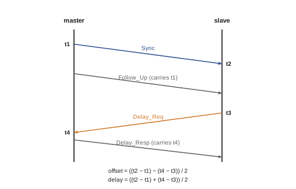
When a lidar on one processor and an IMU on another timestamp their data, those timestamps can only be compared if the two clocks agree. Crystal oscillators drift by tens of parts per million, so two free-running clocks can disagree by several milliseconds after a few minutes. Network Time Protocol keeps computers within about a millisecond over the internet and better on a local network, which is enough for logging but not for sensor fusion at speed. The Precision Time Protocol (PTP, IEEE 1588) synchronizes devices on a local network to well under a microsecond when hardware timestamping is used. A master clock and each slave exchange timestamped messages, and the slave computes its offset and the path delay:
Here \( t_1 \) is when the master sent Sync, \( t_2 \) when the slave received it, \( t_3 \) when the slave sent Delay_Req and \( t_4 \) when the master received it. The calculation assumes the path delay is the same in both directions; asymmetry shows up directly as offset error. Hardware timestamping in the network interface removes the variable software delays that would otherwise dominate. On Linux, the linuxptp tools (ptp4l and phc2sys) implement PTP and IEEE 802.1AS, and many cameras, lidars and industrial devices support PTP natively.
# PTP offset and delay from four timestamps (nanoseconds)
exchanges = [  # t1 master send, t2 slave receive, t3 slave send, t4 master receive
    (1_000_000_000, 1_000_012_450, 1_000_500_000, 1_000_487_710),
    (1_125_000_000, 1_125_012_430, 1_125_500_000, 1_125_487_730),
    (1_250_000_000, 1_250_012_470, 1_250_500_000, 1_250_487_690),
]
for t1, t2, t3, t4 in exchanges:
    offset = ((t2 - t1) - (t4 - t3)) / 2
    delay = ((t2 - t1) + (t4 - t3)) / 2
    print("offset %+7.0f ns   path delay %6.0f ns" % (offset, delay))
# a 400 ns asymmetry (forward path longer) appears as a 200 ns offset error
fwd, back = 1200, 800
print("asymmetry error: %.0f ns" % ((fwd - back) / 2))offset +12370 ns path delay 80 ns offset +12350 ns path delay 80 ns offset +12390 ns path delay 80 ns asymmetry error: 200 ns
The slave's clock is about 12 µs ahead of the master's, with a path delay of about 80 ns, consistent with a direct link of roughly 15 m of cable; the servo in ptp4l would now steer the slave clock to remove the offset, typically converging to tens of nanoseconds with hardware timestamps. For a robot moving at 2 m/s, a 1 ms timestamp error between camera and odometry is a 2 mm position error, and at 1 rad/s of rotation a 1 ms error misplaces a landmark 10 m away by 1 cm, which is why tightly coupled visual-inertial estimators synchronize sensors in hardware, with trigger lines or PTP, rather than relying on software timestamps.
Worked problem
Clock drift without synchronization
Two sensor processors have crystals with ±30 ppm tolerance. If they are synchronized once at power-up and never again, what is the worst-case disagreement after 10 minutes?
Show solution
- Worst-case relative drift: \( 30 + 30 = 60 \) ppm \( = 60 \times 10^{-6} \).
- After 600 s: \( 600 \times 60 \times 10^{-6} = 0.036 \) s.
Answer: Up to 36 ms, far too much for fusing a 200 Hz IMU with a camera. Continuous synchronization (PTP, a shared trigger, or at least periodic NTP) is essential.
Common mistakes
MistakeTreating a shared bus or network as having zero delay
InsteadInclude worst-case network latency and blocking in every distributed budget.
MistakeRunning CAN near 100 % load
InsteadKeep load below about 50 to 70 % and analyse worst-case message latency.
MistakeLeaving ROS 2 QoS at defaults for command topics
InsteadChoose reliability, history depth, deadline and lifespan deliberately.
MistakeFusing sensor data with unsynchronized software timestamps
InsteadUse PTP with hardware timestamps or hardware triggers.
MistakeIgnoring path asymmetry in PTP
InsteadCalibrate or compensate asymmetric delays, which appear as offset error.
Summary and key terms
- A real-time network bounds delivery time for every message, using priority arbitration, master scheduling or time-aware switching.
- CAN is fixed-priority and non-preemptive, so response-time analysis applies with one frame of blocking.
- An 8-byte classic CAN frame at 1 Mbit/s takes up to 135 µs, and load should stay well below 100 %.
- EtherCAT processes one frame on the fly through every device, giving sub-millisecond cycles and distributed clocks.
- TSN adds time synchronization, scheduled queues and frame preemption to standard Ethernet.
- DDS and ROS 2 QoS settings for reliability, history, deadline and lifespan decide real-time behaviour.
- PTP with hardware timestamps synchronizes clocks to well under a microsecond so distributed measurements can be fused.
- Arbitration
- The rule that decides which node may transmit when several want to.
- Bus load
- The fraction of time a bus is occupied by transmissions.
- Bit stuffing
- Extra bits CAN inserts to keep receivers synchronized, lengthening frames.
- EtherCAT
- An Ethernet fieldbus in which devices process one frame on the fly.
- Distributed clocks
- EtherCAT's mechanism for synchronizing all devices' time.
- TSN
- Time-sensitive networking: IEEE 802.1 standards for real-time Ethernet.
- QoS
- Quality-of-service settings that control middleware delivery behaviour.
- Lifespan
- A QoS setting that discards samples older than a set age.
- PTP
- Precision Time Protocol, IEEE 1588, for sub-microsecond clock synchronization.
- Hardware timestamping
- Recording packet times in the network interface rather than in software.
Practice problems
Work each problem on paper first, then reveal the answer to check.
Worst-case time for a 4-byte standard CAN frame at 500 kbit/s?
Show answer
\( (55 + 40) \times 2 \) µs = 190 µs.
Which CAN message wins arbitration, ID 0x120 or 0x0F0?
Show answer
0x0F0.
Why can a high-priority CAN frame be blocked?
Show answer
A frame already on the bus cannot be interrupted.
How does EtherCAT avoid per-device frames?
Show answer
Devices read and insert data on the fly into one passing frame.
Name the TSN standard for scheduled switch queues.
Show answer
IEEE 802.1Qbv.
Which QoS keeps only the newest sample?
Show answer
KEEP_LAST with depth 1.
t2 − t1 = 1,000 ns and t4 − t3 = 600 ns. Offset and delay?
Show answer
Offset 200 ns, delay 800 ns.
Two ±20 ppm clocks drift apart by up to how much per minute?
Show answer
2.4 ms.
Which Linux tools implement PTP?
Show answer
linuxptp: ptp4l and phc2sys.
Why prefer best effort for a high-rate command topic?
Show answer
Retransmitting stale commands adds delay; the next sample replaces the last.
Lesson quiz · 5 questions
Score 60% or more to complete this lesson.
Create a free account to save your progress, take quizzes and earn a certificate.