
ROB-320 · Lesson 12 of 12 · 33 min
Capstone: the real-time architecture of a robot joint controller
This capstone brings the course together in one design: the embedded software for a smart joint module of a collaborative robot arm. Each module contains a brushless motor, a gearbox, an absolute encoder on the output side, current sensors, a brake, a temperature sensor and a microcontroller that talks to the arm's main controller over EtherCAT or CAN FD. The task is to turn the module's requirements into a set of interrupts and tasks, choose priorities, show by analysis that every deadline is met with margin, check the end-to-end latency budget, plan memory and protection, define fault handling, and specify how the design will be verified. The approach is the one a real team would follow, and the numbers, while illustrative, are typical of current hardware.
Requirements
The module's timing and safety requirements, agreed with the controls and safety engineers, are:
- R1: the current (torque) loop shall update the PWM duty cycle every 50 µs (20 kHz), synchronized to the PWM centre.
- R2: the velocity and position loops shall run every 250 µs (4 kHz), and the time from encoder sample to updated current reference shall not exceed 120 µs.
- R3: commands from the main controller arrive every 1 ms; the module shall respond with feedback within the same cycle and shall decelerate to standstill if no valid command arrives for 3 ms.
- R4: the safety monitor shall check position, velocity, current and temperature limits every 1 ms and command safe torque off within 2 ms of a limit violation.
- R5: diagnostics and logging shall run at 100 Hz and may be delayed, but shall not delay any other function.
- R6: total processor utilization shall stay below 75 % so that future features fit, and every hard deadline shall have at least 20 % margin in its worst-case response time.
Architecture
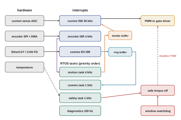
The processor is a 480 MHz Cortex-M7 with tightly coupled memory, running FreeRTOS. Following lesson 4's advice, the 20 kHz current loop runs in an interrupt rather than a task, because switching a task in and out 20,000 times a second would waste several per cent of the processor. The encoder is read by SPI with DMA, triggered by a timer, so the read itself costs no processor time. Communication receive is interrupt-driven with a lock-free ring buffer (lesson 7). Everything else runs as RTOS tasks with deadline-monotonic priorities. Safe torque off is implemented in hardware, through a gate-driver enable line driven by both the safety task and an independent window watchdog, so that a software failure cannot prevent it (lesson 11).
| Activity | Type | Period or minimum gap (µs) | Deadline (µs) | WCET (µs) | Priority |
|---|---|---|---|---|---|
| Current loop | ISR (ADC complete) | 50 | 25 | 9 | ISR 1 (highest) |
| Encoder DMA complete | ISR | 250 | 20 | 3 | ISR 2 |
| Communications receive | ISR (sporadic) | 100 | 100 | 4 | ISR 3 |
| Motion (velocity and position) | Task | 250 | 120 | 42 | Task 4 (highest task) |
| Communications | Task | 1000 | 400 | 110 | Task 3 |
| Safety monitor | Task | 1000 | 1000 | 55 | Task 2 |
| Diagnostics and logging | Task | 10000 | 10000 | 850 | Task 1 |
The motion task's deadline of 120 µs comes straight from R2: it is released by the encoder DMA interrupt and must produce the new current reference within the budget. Communications gets a 400 µs deadline so that feedback is ready well before the next 1 ms command. Execution times were measured as in lesson 2: maximum over a 24-hour soak with all interfaces at full load and the cache flushed periodically, plus 30 % margin, with context-switch time added for tasks.
Shared data and blocking
The design limits sharing deliberately. The motion task passes the current reference to the current-loop interrupt through a double buffer with an atomic index swap, so neither blocks the other. The communications interrupt passes frames to the communications task through a single-producer single-consumer ring buffer. Two mutexes, both with priority inheritance and used only by tasks, protect the parameter set (critical section 10 µs in the communications task) and the statistics block (critical section 15 µs in the diagnostics task). The motion task reads parameters only through a copy refreshed by the communications task between cycles, so it never takes a mutex. The longest interrupts-disabled section anywhere is 2 µs, in the double-buffer swap, and it is counted as blocking for every interrupt.
Worked problem
Blocking terms
Using the design above, what blocking term applies to the motion task, the communications task and the safety task?
Show solution
- Motion task: takes no mutex, so it can only be delayed by the 2 µs interrupts-off section: \( B = 2 \) µs.
- Communications task: can wait for the statistics mutex held by diagnostics: \( B = 15 \) µs.
- Safety task: reads the parameter copy and statistics through the mutexes, so it can be blocked by the longest lower-priority critical section, diagnostics at 15 µs: \( B = 15 \) µs.
Answer: B is 2 µs for motion, 15 µs for communications and 15 µs for safety. Keeping the motion task free of mutexes is what keeps its blocking term so small.
Schedulability analysis
With priorities, execution times and blocking terms fixed, response-time analysis (lesson 5) checks every activity, treating interrupts as the highest-priority sporadic tasks.
import math
# name, C, T, D, B (all in microseconds); highest priority first
acts = [
    ("ISR current",      9,    50,    25,  2),
    ("ISR encoder",      3,   250,    20,  2),
    ("ISR comms rx",     4,   100,   100,  2),
    ("motion task",     42,   250,   120,  2),
    ("comms task",     110,  1000,   400, 15),
    ("safety task",     55,  1000,  1000, 15),
    ("diagnostics",    850, 10000, 10000,  0),
]
U = sum(C / T for _, C, T, _, _ in acts)
print("total utilization: %.1f %%" % (100 * U))
worst_margin = 1.0
for i, (name, C, T, D, B) in enumerate(acts):
    R = C + B
    while True:
        nxt = C + B + sum(math.ceil(R / Tj) * Cj for _, Cj, Tj, _, _ in acts[:i])
        if nxt == R or nxt > D:
            R = nxt
            break
        R = nxt
    margin = (D - R) / D
    worst_margin = min(worst_margin, margin)
    print("%-13s R = %5d us  D = %5d us  margin %5.1f %%  %s"
          % (name, R, D, 100 * margin, "ok" if R <= D else "MISS"))
print("smallest margin: %.1f %%" % (100 * worst_margin))total utilization: 65.0 % ISR current R = 11 us D = 25 us margin 56.0 % ok ISR encoder R = 14 us D = 20 us margin 30.0 % ok ISR comms rx R = 18 us D = 100 us margin 82.0 % ok motion task R = 69 us D = 120 us margin 42.5 % ok comms task R = 227 us D = 400 us margin 43.2 % ok safety task R = 349 us D = 1000 us margin 65.1 % ok diagnostics R = 1980 us D = 10000 us margin 80.2 % ok smallest margin: 30.0 %
Total utilization is 65 %, inside R6's 75 % limit. Every activity meets its deadline with at least 20 % margin, but the analysis exposes one tight spot: the encoder interrupt, whose 20 µs deadline is the shortest in the system, sits below the current-loop interrupt, which is kept highest because it is synchronized to the PWM. Its 30 % margin is the smallest in the system, so adding work to the current-loop interrupt would erode it first. The design notes record this as the first thing to recheck after any change.
Worked problem
What if the current loop grows?
A new feature adds 4 µs to the current-loop interrupt, making it 13 µs. Recompute the encoder interrupt's response time (C = 3, B = 2, D = 20; the only higher-priority activity is the current loop, T = 50).
Show solution
- Start: \( R = 3 + 2 = 5 \).
- Iterate: \( 5 + \lceil 5/50 \rceil \cdot 13 = 18 \); then \( 5 + \lceil 18/50 \rceil \cdot 13 = 18 \).
- Margin: \( (20 - 18)/20 = 10\,\% \).
Answer: R = 18 µs: the deadline is still met, but the margin falls to 10 %, below R6's 20 %. Options are to move part of the new work out of the interrupt, or to put the encoder interrupt above the current loop in deadline-monotonic order (its deadline is shorter). That gives the encoder R = 5 µs and the current loop \( 13 + 2 + 3 = 18 \) µs against its 25 µs deadline, a 28 % margin.
End-to-end latency budget
R2 requires 120 µs from encoder sample to new current reference, and the current loop then applies it at its next update. The chain and its worst cases are:
| Stage | Worst case (µs) | Source |
|---|---|---|
| Encoder conversion and SPI transfer by DMA | 14 | Encoder datasheet plus 10 MHz SPI, 120 bits |
| Encoder DMA interrupt response | 14 | Response-time analysis |
| Motion task wake-up and run | 69 | Response-time analysis, from its release |
| Double-buffer publish | 1 | Measured |
| Total to new current reference | 98 | Requirement R2: 120 µs |
| Wait for next current-loop update | 50 | One current-loop period, worst case |
| Sample to applied torque | 148 | Used in the velocity-loop phase budget |
The 98 µs worst case leaves 22 µs, about 18 %, against R2. The full sample-to-torque delay of 148 µs is what the controls engineers use in the velocity-loop design: at a crossover of 150 Hz it costs \( 360^{\circ} \times 150 \times 0.000148 = 8.0^{\circ} \) of phase margin (lesson 1), which they have already included.
# Check the latency budget and the phase cost of the full delay
stages = {"encoder + SPI DMA": 14, "encoder ISR response": 14,
          "motion task": 69, "publish": 1}
to_ref = sum(stages.values())
req = 120
print("sample to current reference: %d us (requirement %d us, margin %.0f %%)"
      % (to_ref, req, 100 * (req - to_ref) / req))
to_torque = to_ref + 50
fc = 150.0
print("sample to torque: %d us; phase cost at %.0f Hz: %.1f deg"
% (to_torque, fc, 360 * fc * to_torque * 1e-6))sample to current reference: 98 us (requirement 120 us, margin 18 %) sample to torque: 148 us; phase cost at 150 Hz: 8.0 deg
Memory and protection plan
All kernel objects are created statically at start-up, and no heap is used after initialization (lesson 8). The current-loop interrupt, the motion task and their data live in tightly coupled memory, so their timing is free of cache effects. Stacks were sized by call-graph analysis with 50 % margin and are monitored by high-water marks reported in diagnostics; the Armv7-M MPU places a guard region below each task stack and gives the communications and diagnostics tasks access only to their own data and the shared buffers, so a parsing bug in communications cannot overwrite the motion task's state. DMA buffers sit in a non-cacheable region.
Worked problem
RAM budget
Stacks are: motion 1 kB, communications 2 kB, safety 1 kB, diagnostics 4 kB, idle 256 B, interrupt (main) stack 2 kB. The ring buffer holds 64 frames of 72 bytes, the trace buffer is 32 kB and other data uses 18 kB. Will it fit in 128 kB of RAM with at least 25 % free?
Show solution
- Stacks: \( 1024 + 2048 + 1024 + 4096 + 256 + 2048 = 10{,}496 \) bytes.
- Ring buffer: \( 64 \times 72 = 4608 \) bytes.
- Total: \( 10{,}496 + 4608 + 32{,}768 + 18{,}432 = 66{,}304 \) bytes, about 65 kB.
- Free: \( 131{,}072 - 66{,}304 = 64{,}768 \) bytes, about 49 %.
Answer: About 65 kB used and 49 % free, meeting the 25 % target with room for a larger trace buffer during development.
Fault handling
| Fault | Detected by | Detection time | Reaction |
|---|---|---|---|
| Motion task overrun | xTaskDelayUntil return value | Next cycle (250 µs) | Hold last reference; safe torque off after 3 in a row |
| Command stream lost | Command age check in motion task | 3 ms (R3) | Decelerate to standstill, then brake |
| Encoder fault or implausible jump | CRC and rate check in encoder ISR | 250 µs | Safe torque off and brake |
| Over-current, over-speed, over-temperature | Safety task limit checks | Up to 1 ms | Safe torque off within 2 ms (R4) |
| Hung software | Supervisor and window watchdog | Up to 14 ms | Hardware safe torque off and reset |
| Stack overflow or illegal access | MPU fault | Immediate | Log context, safe torque off, reset |
The hung-software path is the slowest, at up to 14 ms, so the arm's safety concept must not rely on it for fast stops; the faster limit checks in the safety task and the hardware over-current comparator in the gate driver handle the urgent cases, and the watchdog is the backstop for everything else.
Verification plan
The design is verified at several levels, each producing evidence linked back to the requirements:
- Static: MISRA C checks and static analysis on every commit; worst-case stack analysis; review of interrupt priorities and the response-time analysis, rerun automatically from a table of measured WCETs.
- Unit: host tests of the control law, the double buffer, the ring buffer and the supervisor state machine, including fault injection, with structural coverage measured.
- Timing on target: debug-pin and trace measurements of every activity's execution and response time; a 24-hour soak at maximum interface load with overrun counters, high-water marks and maximum response times logged; cyclic comparison of measured maxima against the analysis.
- Hardware in the loop: the controller drives a real-time simulation of the motor, gearbox and arm load; tests inject encoder faults, command dropouts, CAN or EtherCAT errors and stalled tasks, and confirm each reaction and its timing against the fault table.
- System: on the real joint and then the full arm, step responses, stopping distances and safe-torque-off timing are measured and compared with the requirements, under the relevant functional safety process (lesson 11).
Worked problem
Turning a requirement into a test
Write a pass criterion for requirement R4 that a test engineer can apply on the hardware-in-the-loop rig.
Show solution
- Stimulus: drive the simulated joint current above its limit by 10 % in a step, at random phases relative to the safety task.
- Measurement: time from the simulated current crossing the limit to the gate-driver enable line going low, captured on an oscilloscope.
- Repetitions: 1,000 trials, including trials with full communications and diagnostics load.
Answer: Pass if the maximum measured time over 1,000 trials is at most 2.0 ms and no trial fails to trip, with the measured maximum also below the analysed worst case. Record the distribution, not just the pass result, so later changes can be compared.
Reflecting on the design
The capstone shows the pattern that runs through the course. Requirements are turned into explicit timing numbers. Work is placed where its timing can be guaranteed: hardware for the fastest and most safety-critical paths, interrupts for the next tier, prioritized tasks for the rest, and the main Linux computer for planning and perception (lesson 9). Sharing is minimized and, where it remains, made non-blocking or bounded. Analysis shows the design can work, measurement shows the implementation does, and fault handling and testing show what happens when it does not. The same method scales from a single joint module to a whole robot, where the main controller's real-time Linux, the EtherCAT network and each module's firmware become stages in one end-to-end budget.
Common mistakes
MistakePlacing the 20 kHz current loop in an RTOS task
InsteadRun it in an interrupt or hardware to avoid switching overhead and jitter.
MistakeLetting the fastest task take mutexes
InsteadPass data through double buffers or copies so its blocking term stays tiny.
MistakeChecking only utilization
InsteadRun response-time analysis with interrupts and blocking for every activity.
MistakeRelying on the watchdog for fast safety stops
InsteadUse limit checks and hardware paths for urgent faults; the watchdog is the backstop.
MistakeWriting requirements without pass criteria
InsteadDefine stimulus, measurement, repetitions and pass limits for each timing requirement.
Summary and key terms
- A joint controller's requirements translate into periods, deadlines, latency budgets and margins.
- The fastest loops run in interrupts or hardware, the rest in prioritized RTOS tasks.
- Deadline-monotonic priorities and response-time analysis with interrupts and blocking show every deadline is met.
- Non-blocking double and ring buffers keep the motion task's blocking term to the interrupts-off time.
- The end-to-end budget from encoder sample to torque feeds back into the control design as phase margin.
- Static allocation, tightly coupled memory, stack analysis and MPU regions make memory behaviour predictable.
- A fault table and a layered verification plan link every requirement to detection, reaction and evidence.
- Smart joint module
- A robot joint with its own motor, sensors and control processor.
- Safe torque off
- A safety function that removes the motor's ability to produce torque.
- Deadline-monotonic
- Assigning higher priority to activities with shorter deadlines.
- Activity set
- All interrupts and tasks with their timing parameters, used for analysis.
- Double buffer
- Two buffers swapped atomically so a writer and reader never block each other.
- End-to-end latency
- The delay along a chain of stages from a sensor sample to an actuator action.
- Margin
- The fraction of a deadline left unused by the worst-case response time.
- Fault table
- A list of faults with their detection, detection time and reaction.
- Pass criterion
- The measurable condition a test must meet to show a requirement is satisfied.
- Traceability
- Linking each requirement to its design, analysis and test evidence.
Practice problems
Work each problem on paper first, then reveal the answer to check.
Why does the current loop run in an interrupt here?
Show answer
Task switching at 20 kHz would waste processor time and add jitter.
What is the motion task's blocking term and why so small?
Show answer
2 µs; it takes no mutexes, only the interrupts-off section applies.
What total utilization did the analysis report?
Show answer
65 %.
Which activity has the tightest deadline?
Show answer
The encoder DMA interrupt, at 20 µs.
What change would protect the encoder interrupt if the current loop grows?
Show answer
Put it above the current loop in deadline-monotonic order, or move work out of the interrupt.
What is the sample-to-reference worst case and margin?
Show answer
98 µs, about 18 % against 120 µs.
What phase does 148 µs cost at 150 Hz?
Show answer
About 8.0°.
Where do the current-loop code and data live and why?
Show answer
Tightly coupled memory, for cache-free predictable timing.
What is the slowest fault-detection path?
Show answer
The watchdog, up to 14 ms.
Give the three parts of a timing pass criterion.
Show answer
Stimulus, measurement and pass limit (with repetitions).
Lesson quiz · 5 questions
Score 60% or more to complete this lesson.
Create a free account to save your progress, take quizzes and earn a certificate.