
ROB-360 · Lesson 1 of 12 · 31 min
Robot software architecture
A working robot is a software system long before it is a mechanical one. A warehouse robot that picks totes may run eighty processes on three computers, talk to a dozen microcontrollers, log several gigabytes an hour and receive updates from a fleet server. Almost every hard problem a robotics team faces after the first demonstration is a software problem: making that system reliable, testable, changeable and safe as it grows. This course is about the engineering discipline that makes robot software dependable, from architecture and requirements to testing, simulation, continuous integration, field operations and security.
ROB-110 introduced the tools: Linux, Python, Git and the ROS 2 graph of nodes, topics, services and actions, with launch files and lifecycle nodes. This course assumes that toolkit and asks the next question: how should a whole robot's software be organized so that a team of people can build it, test it and keep it working for years? This first lesson looks at architecture, the set of high-level decisions about how the system is divided into parts, how those parts communicate and which part is responsible for what.
What architecture is and why robots need it
Software architecture is the structure of a system: its components, the interfaces between them, and the rules that govern how they interact and evolve. It is the set of decisions that are expensive to change later. Choosing a variable name is not architecture; choosing whether perception and planning run in one process or two, whether the controller talks to motors through a hardware abstraction layer or directly, and whether the robot can keep driving when it loses its network connection, are architecture.
Robots make architecture especially important for four reasons. First, they combine many disciplines (perception, estimation, planning, control, user interface, fleet management), each with its own experts, so clear boundaries let specialists work in parallel. Second, they have mixed timing needs: a current loop must run every 50 µs while a route planner may take a second, and these cannot share a thread. Third, they act in the physical world, so a software fault can injure someone; the architecture must contain faults and make the safe behaviour easy to guarantee. Fourth, robots live a long time and change constantly: sensors are replaced, algorithms improve, customers ask for features. A good architecture lets a team change one part without breaking the rest.
Layered architectures
The oldest and still most common organizing idea is layering. Each layer provides services to the layer above and uses services from the layer below, and dependencies point in one direction only. A typical robot stack has a hardware layer (motors, encoders, cameras), a driver and hardware abstraction layer that presents those devices through standard interfaces, a control layer that closes fast feedback loops, a functional layer of perception, estimation and planning, an executive or behaviour layer that sequences tasks and handles failures, and an application or mission layer that talks to people and fleet systems.
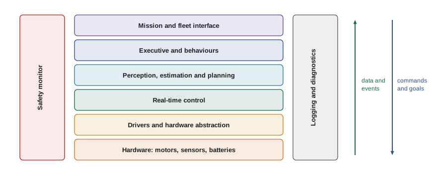
Layering gives two big benefits. Lower layers can be tested and reused without the upper ones, and upper layers can be developed against a stable interface while the hardware is still changing. The classic three-layer architecture from the 1990s, with a deliberative planner on top, an executive in the middle and reactive skills at the bottom, captures the same idea at a coarser grain. The weakness of strict layering is latency: forcing every sensor reading to climb through every layer before an action is chosen is too slow for reflexes, so real robots also have short paths, such as a bumper wired straight to the motor controller or a safety scanner that cuts power on its own.
Component-based and message-based design
Within the layers, modern robot software is built from components: separately developed units with well-defined inputs, outputs and parameters, connected at run time. ROS 2 nodes are components; so are the plugins of a navigation stack and the controllers of ros2_control. Components communicate through messages with defined types, which decouples them in three ways. In space, a publisher does not know which subscribers exist. In time, with suitable quality-of-service settings a late subscriber can still receive the last message. In implementation, a component written in C++ can talk to one written in Python.
Message-based design has costs as well. Every message is copied or at least serialized, which adds latency and CPU load. The graph of topics can grow until nobody understands it, and the system's real behaviour emerges from timing interactions that no single component controls. Good architectures keep the graph legible: a modest number of well-named topics with documented rates and units, clear ownership of each topic, and as few cycles as possible.
| Interaction style | ROS 2 mechanism | Use for | Avoid for |
|---|---|---|---|
| Streaming data | Topic (publish/subscribe) | Sensor data, state estimates, commands at a fixed rate | Requests that need a reply |
| Request and reply | Service | Short queries and configuration changes | Anything that takes more than a moment |
| Long-running goal | Action | Navigation goals, arm motions, docking | High-rate streaming |
| Configuration | Parameter | Gains, thresholds, frame names | Values that change every cycle |
| Shared state | tf2 transforms | Coordinate frames over time | Arbitrary non-geometric data |
Nodes, processes and composition
An architecture must also decide how components map onto operating-system processes and computers. Running every node in its own process gives isolation: a crash in perception does not kill the controller, and each process can be restarted separately. But inter-process messages cost serialization and copying, which matters for large data such as point clouds and images. ROS 2 composition lets several nodes be loaded into one container process, where messages can be passed by pointer with zero copies. The usual pattern is to compose tightly coupled, high-bandwidth pipelines, such as a camera driver, rectification and a detector, and to keep safety-relevant and independently restartable parts in separate processes.
Lifecycle (managed) nodes, introduced in ROB-110, add a standard state machine of unconfigured, inactive, active and finalized states. Their architectural value is orchestration: a system manager can configure every node, check that all are ready, and only then activate them together, and it can deactivate a misbehaving node without destroying it. Navigation stacks use a lifecycle manager in exactly this way.
Worked problem
Bandwidth decides composition
A depth camera publishes 640 × 480 point clouds at 30 Hz, with 16 bytes per point. A filter node and a segmentation node consume every cloud. Estimate the data copied per second if each consumer runs in its own process, and explain what composition saves.
Show solution
- Points per cloud: \( 640 \times 480 = 307\,200 \). Bytes per cloud: \( 307\,200 \times 16 \approx 4.9 \) MB.
- Per second at 30 Hz: \( 4.9 \times 30 \approx 147 \) MB/s for one copy.
- Two separate consumer processes each receive a serialized copy: about 295 MB/s of copying, plus serialization CPU time.
- Composed into one process with intra-process communication, the clouds can be shared by pointer, so the per-cloud copy largely disappears.
Answer: About 300 MB/s of copying is avoided. That is why high-bandwidth pipelines are composed, while low-rate, safety-relevant nodes stay in their own processes for isolation.
Hardware abstraction and ros2_control
A hardware abstraction layer (HAL) hides the details of particular devices behind standard interfaces, so that higher layers ask for 'joint 3 velocity' rather than 'write 0x2A to register 0x60FF of the drive on CAN node 7'. Abstraction lets the same controller run on the real robot, on a different motor drive, or in simulation. It also gives one place to enforce limits and convert units.
In ROS 2 the standard framework for this is ros2_control. A hardware interface plugin, written once per robot, exposes state interfaces (such as position and velocity of each joint) and command interfaces (such as effort or velocity commands). A controller manager loads controller plugins, for example a joint trajectory controller or a differential drive controller, and runs them in a real-time loop at a fixed rate, reading states, computing commands and writing them back. Swapping the hardware interface for a simulation interface, such as the one provided with Gazebo, lets the identical controller configuration run against a simulated robot, which is a foundation of the simulation and testing workflows later in this course.
# controllers.yaml for ros2_control (listing)
controller_manager:
  ros__parameters:
    update_rate: 500            # Hz, the real-time loop
    joint_state_broadcaster:
      type: joint_state_broadcaster/JointStateBroadcaster
    diff_drive_controller:
      type: diff_drive_controller/DiffDriveController
diff_drive_controller:
  ros__parameters:
    left_wheel_names: ["left_wheel_joint"]
    right_wheel_names: ["right_wheel_joint"]
    wheel_separation: 0.42      # m
    wheel_radius: 0.08          # m
    linear.x.max_velocity: 1.2  # m/s
    cmd_vel_timeout: 0.5        # s: stop if commands go stale
Separating concerns: safety, timing and data
Three cross-cutting concerns deserve their own architectural decisions. The first is safety. Safety functions such as emergency stop, speed and separation monitoring and safe torque off should be as simple and independent as possible, often running on separate certified hardware, so that the complex software above them cannot defeat them. The rest of the software is designed on the assumption that it can fail, and the safety layer catches the failure. The second is timing. Components with hard deadlines, such as current and joint control, run on real-time cores or microcontrollers (ROB-320), while best-effort components run on general-purpose computers; the interface between them must be designed so that late or missing commands are handled safely, for example by a command timeout that stops the motors. The third is data: decide early which data is logged, at what rate, with what timestamps, because diagnosing field failures depends entirely on it.
Worked problem
A command timeout budget
A planner publishes velocity commands at 20 Hz. The base controller is set to stop the robot if no command arrives for 0.5 s. At 1.2 m/s, how far can the robot travel on a stale command before it begins to stop, and how many consecutive messages must be lost?
Show solution
- Distance at full speed in 0.5 s: \( 1.2 \times 0.5 = 0.6 \) m.
- Commands are sent every 0.05 s, so 0.5 s corresponds to 10 message periods.
- The timeout triggers only if about 10 consecutive commands are missed; one or two dropped messages are tolerated.
Answer: Up to 0.6 m on a stale command, after about 10 missed messages. If that is too far for the application, shorten the timeout or slow down, and add braking distance to the safety budget.
Architectural styles in practice
Several patterns recur in robot software. Pipelines (sense, then estimate, then plan, then act) are easy to reason about but can hide latency. Blackboards share a common world model that components read and write, which simplifies coordination but needs careful locking and ownership rules. Behaviour trees, used by many navigation and manipulation executives, organize task logic as a tree of sequences, fallbacks and conditions that is easy to read and extend; state machines are simpler for small, well-bounded tasks. Client and server patterns connect robots to fleet managers, usually through a gateway that translates between the robot's internal messages and an external API, so that network problems never block the robot's internal loops.
A useful test for any architecture is the 'what if' list. What if the network drops for a minute? What if a camera stops publishing? What if the planner takes ten times longer than usual? What if a new sensor is added next year? An architecture that has a clear answer to each question, ideally one the team has tested, is in good shape. Lesson 2 shows how to record these decisions so that they survive staff changes, and lesson 4 shows how to test the answers.
Worked problem
Counting interfaces
A team plans 12 components. In design A every component may talk to every other directly. In design B components are grouped into 4 layers of 3, and each component talks only to components in its own layer or the layer directly below. Compare the maximum number of pairwise interfaces.
Show solution
- Design A: pairs among 12 components: \( 12 \times 11 / 2 = 66 \).
- Design B, within layers: each layer has \( 3 \times 2 / 2 = 3 \) pairs, so 12 in total.
- Between adjacent layers: 3 layer boundaries with \( 3 \times 3 = 9 \) pairs each, so 27.
- Design B total: \( 12 + 27 = 39 \).
Answer: Layering cuts the possible interfaces from 66 to 39, and in practice far fewer are used. Fewer interfaces mean fewer things to document, test and break.
Documenting the architecture
An architecture that exists only in the lead developer's head is fragile. Teams document it with a small set of views: a context diagram showing the robot and the external systems and people it interacts with; a component diagram showing major components and their interfaces; a deployment view showing which processes run on which computers; and, for key scenarios such as 'robot receives a delivery goal', a sequence diagram showing the messages exchanged. The C4 model (context, containers, components and code) is a popular, lightweight way to organize these views. For ROS 2 systems, tools that draw the live node graph are useful for checking that the running system matches the intended design, but they are not a substitute for an intentional diagram.
Common mistakes
MistakeLetting every node subscribe to whatever topic it finds useful
InsteadDefine owned interfaces with documented rates, units and frames, and review new dependencies.
MistakePutting the emergency stop logic inside the planner
InsteadKeep safety functions simple, independent and below the complex software.
MistakeRunning a 1 kHz joint controller in a best-effort Python node
InsteadPut hard real-time loops on a real-time thread, core or microcontroller.
MistakeComposing every node into one process to save copies
InsteadCompose high-bandwidth pipelines; keep safety-relevant parts isolated.
MistakeWriting device register access directly into controllers
InsteadUse a hardware abstraction layer such as ros2_control so controllers run on real and simulated hardware.
Summary and key terms
- Architecture is the set of structural decisions that are expensive to change: components, interfaces and their rules.
- Robots need deliberate architecture because they mix disciplines, timing needs and physical risk, and they change for years.
- Layered stacks separate hardware, control, functional, executive and mission concerns, with short paths for reflexes and safety.
- Components communicate through typed messages; choose topics, services, actions and parameters for the right kinds of interaction.
- Map nodes to processes deliberately: compose high-bandwidth pipelines and isolate safety-relevant, restartable parts.
- Hardware abstraction, such as ros2_control, lets the same controllers run on real hardware and in simulation.
- Safety, timing and data logging are cross-cutting concerns that need explicit architectural decisions and documentation.
- Software architecture
- The high-level structure of a system: its components, interfaces and the rules governing them.
- Layered architecture
- An organization in which each layer uses services only from the layer below.
- Component
- An independently developed unit with defined inputs, outputs and parameters.
- Composition
- Running several ROS 2 nodes in one process so messages can be shared without copying.
- Lifecycle node
- A node with a managed state machine that an orchestrator can configure and activate.
- Hardware abstraction layer
- Software that presents devices through standard interfaces, hiding device details.
- ros2_control
- The ROS 2 framework of hardware interfaces, controllers and a real-time controller manager.
- Behaviour tree
- A tree of sequences, fallbacks and conditions used to organize robot task logic.
- Command timeout
- A rule that stops actuators when commands stop arriving within a set time.
- C4 model
- A lightweight way to document architecture as context, container, component and code views.
Practice problems
Work each problem on paper first, then reveal the answer to check.
Name the layers of a typical robot software stack from bottom to top.
Show answer
Hardware, drivers and abstraction, control, perception, estimation and planning, executive, mission and fleet interface.
Why do real robots add short paths that bypass the layers?
Show answer
Strict layering is too slow for reflexes and safety reactions.
Which ROS 2 mechanism suits a docking request that takes 30 s?
Show answer
An action.
What is the main benefit of composing a camera pipeline?
Show answer
Messages can be shared by pointer, avoiding copies and serialization.
What does a lifecycle manager do?
Show answer
Configures, checks and activates managed nodes together, and can deactivate them.
What does a ros2_control hardware interface expose?
Show answer
State interfaces and command interfaces for each joint or actuator.
Why keep safety functions outside the complex software?
Show answer
So that faults in the complex software cannot defeat them.
How far does a robot at 1.0 m/s travel during a 0.3 s command timeout?
Show answer
0.3 m.
How many pairwise links are possible among 8 fully connected components?
Show answer
28.
Name two views used to document an architecture.
Show answer
For example a context diagram and a deployment view.
Lesson quiz · 5 questions
Score 60% or more to complete this lesson.
Create a free account to save your progress, take quizzes and earn a certificate.