
ROB-430 · Lesson 4 of 12 · 37 min
Collaborative robots and shared workspaces
For most of the history of industrial robotics, safety meant keeping people and robots apart. Robots worked inside fenced cells, and interlocked gates stopped the robot whenever someone opened them. Collaborative applications change that assumption: a person and a robot work in the same space, sometimes on the same part, and the safety of the arrangement depends on how the robot senses, limits and adapts its motion. This lesson explains how collaborative applications are classified, how the main safety methods work in numbers, how the international and national standards are organized in Canada and the United States, and how to lay out a shared workstation that is safe, productive and comfortable. It is an introduction for HRI designers, not a substitute for the full standards or for the detailed machinery safety training in HSE-223 and the safety engineering course ROB-450.
Collaborative applications, not collaborative robots
Marketing often speaks of collaborative robots, or cobots, meaning arms designed with features such as force sensing, rounded shapes, low mass and limited power so that they can work near people. The standards take a different view. The 2025 editions of ISO 10218, the international standard for industrial robot safety, deliberately drop the term collaborative robot because collaboration is a property of the application, not of the robot alone. A low-power arm holding a sharp knife or a heavy casting is not safe to work beside just because the arm itself is gentle, while a large conventional robot can be part of a collaborative application if suitable sensing keeps people out of harm's way. The term used now is collaborative application, and every such application needs its own risk assessment covering the robot, the end effector, the workpiece, the layout and the task.
ISO 10218 has two parts. Part 1 covers requirements for robot manufacturers. Part 2 covers robot applications and robot cells, which is where integrators and users work. The 2025 revision of Part 2 absorbed the collaborative-application guidance that had previously been published separately as the technical specification ISO/TS 15066:2016. It also expanded the list of safety functions considerably, introduced cybersecurity requirements where they affect safety, and renamed the safety-rated monitored stop as monitored standstill, a function that applies to collaborative and non-collaborative robots alike.
Four ways to share space
Collaborative operation has traditionally been described through four methods. They can be combined within one application, and the 2025 standards keep the same underlying ideas while adjusting terminology.
| Method | How it works | Typical use |
|---|---|---|
| Monitored standstill (formerly safety-rated monitored stop) | The robot stops and its standstill is monitored by a safety function while a person is in the shared space; it resumes when the person leaves | Operator loads a fixture in the robot's space while the robot waits |
| Hand guiding | The person moves the robot by hand using a guiding device with an enabling switch, at reduced speed | Lifting assistance, positioning heavy parts, teaching by demonstration |
| Speed and separation monitoring (SSM) | Sensors track people; the robot slows or stops so that a protective separation distance is always kept | Mobile or large robots sharing a work area with walking people |
| Power and force limiting (PFL) | Contact is possible, but robot design and control keep forces and pressures below limits for the body region that could be struck | Small-part assembly beside a worker, screwdriving, machine tending |
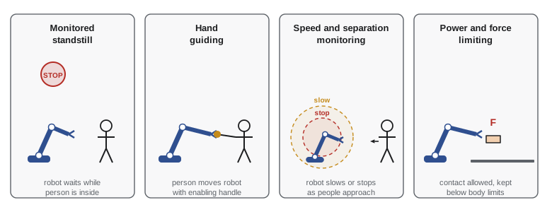
The choice depends on the task. If the person and robot never need to be in the same spot at the same time, monitored standstill or SSM keeps contact from happening at all. If the task requires close proximity and incidental contact is foreseeable, PFL keeps any contact within tolerable limits. Hand guiding suits tasks where human judgement directs the motion. Throughput is affected: SSM slows the robot whenever people are nearby, and PFL restricts speed and payload, so collaborative applications are not always faster than fenced cells. Their benefits come from flexibility, reduced floor space and combining human dexterity with robot strength and repeatability.
Speed and separation monitoring in numbers
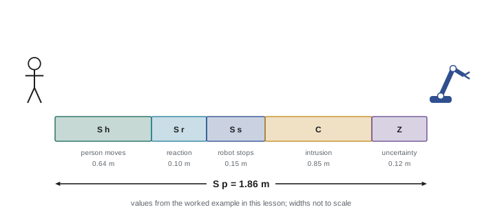
In SSM, the robot must always be far enough from any person that it can stop before contact, even if the person walks straight toward it. The protective separation distance, carried into ISO 10218-2:2025 from ISO/TS 15066, is the sum of several terms:
Here \( S_h \) is the distance the person travels while the system reacts and the robot stops, \( S_r \) is the distance the robot travels during the system's reaction time, \( S_s \) is the robot's stopping distance, \( C \) is an intrusion distance accounting for how far a body part can reach past the sensing field (taken from ISO 13855), and \( Z_d \) and \( Z_r \) account for the position uncertainty of the person sensing and of the robot. In the common constant-speed form, \( S_h = v_h (T_r + T_s) \) and \( S_r = v_r T_r \), where \( T_r \) is the reaction time of the whole system, \( T_s \) the robot's stopping time, \( v_h \) the human approach speed and \( v_r \) the robot speed toward the person. ISO 13855 uses 1.6 m/s as the walking approach speed in many cases, and 2.0 m/s for hand and arm motion close to a sensing device.
Worked problem
Computing a protective separation distance
A robot moves toward a work area at 1.0 m/s. The person-sensing system plus safety controller has a reaction time of 0.10 s, and the robot stops in 0.30 s over a stopping distance of 0.15 m. Take the human approach speed as 1.6 m/s, intrusion distance 0.85 m (for a sensor that may not detect an outstretched arm), and position uncertainties of 0.10 m for the sensor and 0.02 m for the robot. Find the protective separation distance.
Show solution
- Human travel: \( S_h = 1.6 \times (0.10 + 0.30) = 0.64 \) m.
- Robot travel during reaction: \( S_r = 1.0 \times 0.10 = 0.10 \) m.
- Robot stopping distance: \( S_s = 0.15 \) m.
- Add intrusion and uncertainties: \( C + Z_d + Z_r = 0.85 + 0.10 + 0.02 = 0.97 \) m.
- Total: \( S_p = 0.64 + 0.10 + 0.15 + 0.97 = 1.86 \) m.
Answer: About 1.86 m; whenever a person is closer than that along the robot's direction of travel, the robot must already be slowing or stopping.
# Speed and separation monitoring: protective distance vs robot speed
import numpy as np
v_h, T_r, C, Z_d, Z_r = 1.6, 0.10, 0.85, 0.10, 0.02     # m/s, s, m, m, m
a_stop = 3.3                                             # robot deceleration, m/s^2
def protective_distance(v_r):
    T_s = v_r / a_stop                                   # stopping time
    S_s = v_r**2 / (2 * a_stop)                          # stopping distance
    return v_h * (T_r + T_s) + v_r * T_r + S_s + C + Z_d + Z_r
for v_r in (0.25, 0.5, 1.0, 1.5, 2.0):
    print(f"robot {v_r:4.2f} m/s -> S_p = {protective_distance(v_r):.2f} m")
# largest robot speed allowed when the nearest person is 1.5 m away
speeds = np.linspace(0, 2.5, 2501)
ok = speeds[np.array([protective_distance(v) for v in speeds]) <= 1.5]
print(f"max speed with person at 1.50 m: {ok.max():.2f} m/s")robot 0.25 m/s -> S_p = 1.29 m robot 0.50 m/s -> S_p = 1.46 m robot 1.00 m/s -> S_p = 1.87 m robot 1.50 m/s -> S_p = 2.35 m robot 2.00 m/s -> S_p = 2.91 m max speed with person at 1.50 m: 0.55 m/s
SSM depends on the person sensing being safety-rated. Ordinary cameras and lidars used for navigation are not adequate on their own; the sensors and controller must meet functional safety requirements, typically expressed as a performance level under ISO 13849-1 or a safety integrity level under IEC 62061, matched to the risk. Safety laser scanners, light curtains, pressure-sensitive mats and, increasingly, safety-rated 3D sensing systems are used. Fixed sensing devices placed around a cell use the related ISO 13855 formula for minimum distance, \( S = K T + C \), with \( K \) the approach speed in millimetres per second and \( T \) the overall stopping time.
Worked problem
Placing a light curtain
A vertical light curtain with 30 mm resolution guards the opening of a robot cell. The robot plus safety system stops in 0.25 s overall. Using \( S = K T + C \) with \( K = 2000 \) mm/s and \( C = 8(d - 14) \) mm for resolution \( d \), find the minimum distance from the curtain to the hazard.
Show solution
- Intrusion: \( C = 8(30 - 14) = 128 \) mm.
- Distance: \( S = 2000 \times 0.25 + 128 = 628 \) mm.
- Because \( S \) is greater than 500 mm, ISO 13855 allows recalculating with \( K = 1600 \) mm/s: \( 1600 \times 0.25 + 128 = 528 \) mm, which still exceeds 500 mm, so 528 mm is used.
Answer: About 528 mm; check the current edition of ISO 13855 for the exact conditions, as the rules for choosing \( K \) and \( C \) depend on the device and approach direction.
Power and force limiting
In PFL the robot may touch a person, so the question becomes how hard. Contact is classified as transient, when the body part can recoil freely, such as a robot brushing an arm in open space, or quasi-static, when the body part is clamped between the robot and something else, such as a hand trapped against a table. Quasi-static contact is more dangerous because the body cannot move away, so its limits are lower. ISO/TS 15066:2016 published, in its Annex A, body-region limit values for force and pressure based on research on pain onset thresholds, and these values have been widely used to design and verify PFL applications. The table below lists the quasi-static force limits as reported in that 2016 annex, to illustrate the scale; designers must take current values and conditions from the edition of the standard they are applying.
| Body region | Quasi-static force limit (N) | Effective spring constant (N/mm) | Effective mass (kg) |
|---|---|---|---|
| Skull and forehead | 130 | 150 | 4.4 |
| Face | 65 | 75 | 4.4 |
| Neck | 150 | 50 | 1.2 |
| Back and shoulders | 210 | 35 | 40 |
| Chest | 140 | 25 | 40 |
| Abdomen | 110 | 10 | 40 |
| Pelvis | 180 | 25 | 40 |
| Upper arms and elbows | 150 | 30 | 3 |
| Lower arms and wrists | 160 | 40 | 2 |
| Hands and fingers | 140 | 75 | 0.6 |
| Thighs and knees | 220 | 50 | 75 |
| Lower legs | 130 | 60 | 75 |
For transient contact, the 2016 annex allowed higher values, twice the quasi-static values for most regions, but recommended against any contact with the head, face and neck. The annex also gave a simple model linking a force limit to a maximum permissible relative speed. Treating the collision as two masses meeting through a spring of stiffness \( k \), the reduced mass is \( \mu = (1/m_H + 1/m_R)^{-1} \), where \( m_H \) is the effective mass of the body region and \( m_R \) the effective moving mass of the robot plus payload. Equating kinetic energy to spring energy gives
Worked problem
Speed limit for possible hand contact
A robot arm with an effective moving mass of 8 kg (including a 1 kg gripper and part) may make transient contact with a worker's hand. Using the illustrative values in the table, hand effective mass 0.6 kg and stiffness 75 N/mm, and a transient force limit of twice the quasi-static 140 N, estimate the maximum relative speed.
Show solution
- Transient force limit: \( 2 \times 140 = 280 \) N.
- Reduced mass: \( \mu = (1/0.6 + 1/8)^{-1} = (1.667 + 0.125)^{-1} \approx 0.558 \) kg.
- Stiffness in SI units: \( k = 75\,000 \) N/m.
- Speed: \( v_{max} = 280 / \sqrt{0.558 \times 75\,000} \approx 280 / 204.6 \approx 1.37 \) m/s.
Answer: About 1.4 m/s for this simplified model; real verification also measures forces with a calibrated device on the actual application, and sharp edges or pinch points can make even low speeds unsafe.
# PFL: illustrative body-region lookup and maximum transient speed (ISO/TS 15066:2016 Annex A values)
import numpy as np
regions = {   # quasi-static force N, stiffness N/mm, effective mass kg
    "hands and fingers": (140, 75, 0.6),
    "lower arms and wrists": (160, 40, 2.0),
    "upper arms and elbows": (150, 30, 3.0),
    "chest": (140, 25, 40.0),
    "thighs and knees": (220, 50, 75.0),
}
m_robot = 8.0
for name, (F_qs, k_mm, m_h) in regions.items():
    F_tr = 2 * F_qs                                # transient limit, 2x for these regions
    mu = 1 / (1 / m_h + 1 / m_robot)
    v = F_tr / np.sqrt(mu * k_mm * 1000)
print(f"{name:22s} F_tr {F_tr:3d} N mu {mu:5.2f} kg v_max {v:4.2f} m/s")hands and fingers F_tr 280 N mu 0.56 kg v_max 1.37 m/s lower arms and wrists F_tr 320 N mu 1.60 kg v_max 1.26 m/s upper arms and elbows F_tr 300 N mu 2.18 kg v_max 1.17 m/s chest F_tr 280 N mu 6.67 kg v_max 0.69 m/s thighs and knees F_tr 440 N mu 7.23 kg v_max 0.73 m/s
The results show why PFL applications are often limited by the most vulnerable body region that could be struck. If a hand might be clamped or the chest might be struck by a robot that is carrying a heavy payload, speed must be kept low. Designers reduce risk further with padding, rounded tooling, avoiding pinch points near fixtures, and orienting tasks so that the robot's motion is away from the person's head and torso. Verification typically uses a force and pressure measuring device placed at the expected contact points while the robot runs its program.
Standards in Canada and the United States
In Canada, the national standard is CSA Z434:26, Industrial robots, robot applications, and robot cells, published in March 2026. It adopts ISO 10218-1 and ISO 10218-2:2025 with Canadian deviations and supersedes CAN/CSA-Z434-14. CSA standards become legally binding when provincial or territorial occupational health and safety regulations reference them; otherwise they are recognized good practice that inspectors and courts use to judge whether an employer took every reasonable precaution. Provinces regulate most workplaces, so employers must also check provincial rules, such as Ontario's pre-start health and safety review requirements in its industrial establishments regulation. The American counterpart is ANSI/A3 R15.06-2025, which adopts the same ISO parts, so equipment and integration practices are largely aligned across the border.
| Topic | Canada | United States |
|---|---|---|
| National robot safety standard | CSA Z434:26 (adopts ISO 10218-1 and -2:2025) | ANSI/A3 R15.06-2025 (adopts ISO 10218-1 and -2:2025) |
| Collaborative guidance formerly in ISO/TS 15066 | Now within ISO 10218-2:2025 as adopted | Now within ISO 10218-2:2025 as adopted |
| Who enforces workplace safety | Provincial and territorial OHS regulators; federal for federally regulated workplaces | OSHA and state-plan OSHA programs |
| How the standard gains legal force | When referenced in OHS regulations, or as evidence of due diligence | As evidence of recognized hazards and feasible controls |
| Mobile robots in industry | Check current CSA adoption of relevant ISO and ANSI documents | ANSI/A3 R15.08 series for industrial mobile robots |
The point for HRI designers is that the same core technical ideas, risk assessment, the four collaborative methods, separation distances and body-region limits, apply on both sides of the border, while the route by which they become obligations differs. HSE-223 covers machinery safeguarding and lockout in depth, and ROB-450 covers functional safety, safety-rated control systems and safety cases for robots.
Laying out a shared workstation
A safe and effective collaborative workstation starts from the task, not from the robot. Designers list each step, decide who does it, and arrange the space so that the person's work zone and the robot's work zone overlap only where they must. Parts the person handles often should sit within comfortable reach, and the robot should approach the shared zone from the side or front, never from behind the person or at head height. Fixtures should avoid creating pinch points where a hand could be clamped. The robot's speed in the shared zone can be lower than elsewhere, using safety-rated zones and speed limits. Floor markings, signage and lighting help everyone, including visitors and maintenance staff, understand where the collaborative space begins.
Worked problem
Cycle time with SSM slowdowns
A robot cycle takes 20 s at full speed. A worker enters the robot's slowdown zone for 6 s of each cycle, during which the robot runs at 40 per cent speed. Estimate the new cycle time and the throughput loss over a 7.5 hour shift.
Show solution
- Work normally done in 6 s at full speed now takes \( 6/0.4 = 15 \) s.
- New cycle: \( 20 - 6 + 15 = 29 \) s.
- Cycles per shift before: \( 27\,000/20 = 1350 \); after: \( 27\,000/29 \approx 931 \).
- Loss: about \( 1 - 931/1350 \approx 31 \) per cent.
Answer: About 29 s per cycle and a 31 per cent throughput loss, which shows why task layout that keeps people out of the slowdown zone most of the time is as important as the safety function itself.
Human factors from lesson 2 also apply. Workers should be able to see what the robot is about to do, using the communication methods from lesson 3. The robot's pace should not force the worker's pace; a design in which the person waits on the robot is usually preferable to one in which the robot waits impatiently at the worker's elbow. Workers should be involved in the design and trial of the cell, because they know the task, and because involvement builds the trust discussed in lesson 7.
Common mistakes
MistakeCalling an application safe because the robot is sold as a cobot.
InsteadCollaboration belongs to the application; assess the tool, payload, layout and task as well as the arm.
MistakeLeaving out intrusion distance and sensor uncertainty from the separation distance.
InsteadInclude \( C \), \( Z_d \) and \( Z_r \) as well as reaction and stopping terms.
MistakeUsing navigation cameras as the person-detection safety function.
InsteadUse safety-rated sensing with an appropriate performance level or SIL.
MistakeApplying transient contact limits where a body part can be clamped.
InsteadClamping is quasi-static contact, with lower limits; remove pinch points where possible.
MistakeAssuming Canadian and US rules are identical because the ISO parts are shared.
InsteadThe technical content is aligned, but enforcement, deviations and regulatory references differ.
Summary and key terms
- The 2025 ISO 10218 editions speak of collaborative applications rather than collaborative robots.
- ISO 10218-2:2025 absorbed the collaborative guidance of ISO/TS 15066 and renamed the safety-rated monitored stop as monitored standstill.
- The four collaborative methods are monitored standstill, hand guiding, speed and separation monitoring and power and force limiting.
- SSM keeps a protective separation distance \( S_p = S_h + S_r + S_s + C + Z_d + Z_r \).
- PFL limits contact forces and pressures by body region, with lower limits for quasi-static than transient contact.
- Canada uses CSA Z434:26 and the United States ANSI/A3 R15.06-2025, both adopting ISO 10218:2025.
- Workstation layout, communication and worker involvement determine whether a safe cell is also productive and accepted.
- Collaborative application
- An application in which a person and a robot work in a shared space under specific safety measures.
- Monitored standstill
- A safety function that monitors that the robot remains stopped; formerly the safety-rated monitored stop.
- Hand guiding
- Moving a robot directly by hand through a guiding device with an enabling control.
- Speed and separation monitoring
- Keeping a protective distance between robot and person by slowing or stopping the robot.
- Power and force limiting
- Limiting the robot so that any contact stays within body-region thresholds.
- Protective separation distance
- The minimum distance needed for the robot to stop before reaching a person.
- Transient contact
- Contact in which the body part can recoil freely.
- Quasi-static contact
- Contact in which the body part is clamped and cannot move away.
- Intrusion distance
- How far a body part can reach past a sensing field before detection.
- Performance level
- An ISO 13849-1 measure of how reliably a safety function performs.
Practice problems
Work each problem on paper first, then reveal the answer to check.
Name the four methods of collaborative operation.
Show answer
Monitored standstill, hand guiding, speed and separation monitoring, and power and force limiting.
With \( v_h = 1.6 \) m/s, \( T_r = 0.1 \) s and \( T_s = 0.4 \) s, what is \( S_h \)?
Show answer
\( 1.6 \times 0.5 = 0.8 \) m.
A robot at 0.5 m/s with \( T_r = 0.2 \) s travels how far during reaction?
Show answer
0.1 m.
Why are quasi-static limits lower than transient limits?
Show answer
The clamped body part cannot recoil, so force is sustained.
Which document did ISO 10218-2:2025 absorb for collaborative content?
Show answer
ISO/TS 15066:2016.
What is the Canadian national industrial robot standard published in 2026?
Show answer
CSA Z434:26.
What is the US national industrial robot standard published in 2025?
Show answer
ANSI/A3 R15.06-2025.
Light curtain resolution 14 mm: intrusion \( C = 8(d - 14) \)?
Show answer
0 mm.
Reduced mass for a 0.6 kg hand and a 4 kg robot?
Show answer
\( (1/0.6 + 1/4)^{-1} \approx 0.52 \) kg.
Give two layout practices for collaborative cells.
Show answer
Approach from the front or side, avoid pinch points, keep parts in easy reach, mark the collaborative zone.
Lesson quiz · 5 questions
Score 60% or more to complete this lesson.
Create a free account to save your progress, take quizzes and earn a certificate.