
ROB-499 · Lesson 4 of 12 · 27 min
System architecture and design reviews
Once a concept is chosen, the team must turn it into an architecture: the set of subsystems, their responsibilities and the interfaces between them. A clear architecture lets five people work in parallel without constantly breaking each other's work, and it makes resource budgets such as power, mass and computing visible before they are exceeded. This lesson covers physical and functional architecture, interface control, resource budgets with margins, and the three design reviews that structure most capstones: the system requirements review, the preliminary design review and the critical design review. ROB-360 lesson 1 covered software architecture in depth; here the focus is the whole robot.
Functional and physical architecture
The functional architecture, developed from the decomposition in lesson 3, shows what the system does and how information and material flow between functions. The physical architecture shows which hardware and software components implement those functions. Mapping one onto the other is called allocation. A function may be allocated to one component, such as "detect people" to the safety lidar, or split across several, such as "localize", which combines RTK GNSS, wheel odometry, an inertial measurement unit and lidar matching in the estimator from ROB-310. Allocation exposes awkward designs: if a single function is spread across many components owned by different team members, its interfaces will be numerous and fragile.
Team Tern's physical architecture has five subsystems. The mobility subsystem includes the chassis, four wheels with brushed DC gearmotors, two motor drivers and wheel encoders. The power subsystem includes a 24 V lithium iron phosphate battery, a battery management system, a main fuse, an emergency stop circuit and DC-DC converters for 12 V and 5 V loads. The manipulation subsystem includes a four-degree-of-freedom arm with smart servos, a two-finger gripper and the bin. The sensing subsystem includes the RGB-D camera, a 2D safety-rated lidar scanner, an RTK GNSS receiver and an IMU. The computing subsystem includes an embedded computer with a GPU for perception and a microcontroller for low-level motor control and safety monitoring.
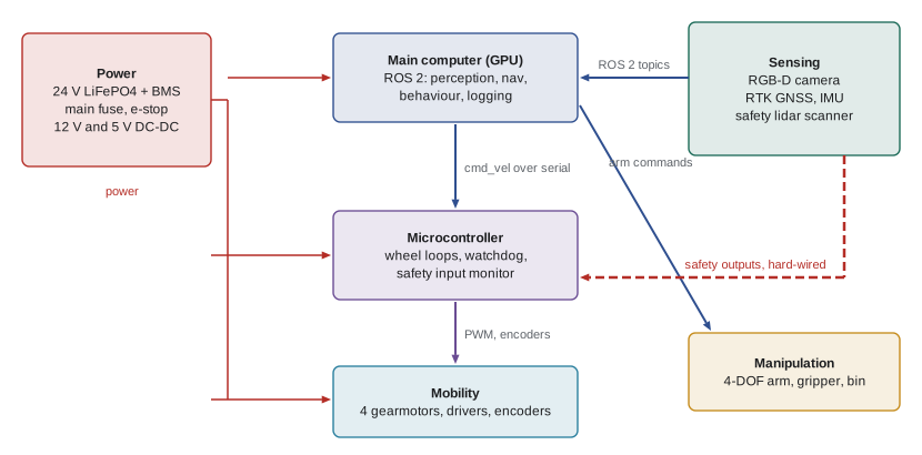
Note one deliberate feature: the safety lidar's protective-field output is wired directly to the microcontroller, which can cut motor power independently of the main computer. This follows the principle from ROB-450 lesson 3 that safety functions should not depend on complex, non-safety-rated software such as a Linux computer running ROS 2. Architecture is where such decisions are made; adding an independent safety path late in the term is far harder.
Interfaces and interface control
Most integration problems are interface problems. A connector wired with the opposite pin order, a message published in degrees when the subscriber expects radians, a bracket designed to a different bolt pattern, or a serial protocol with a mismatched baud rate can each cost days. An interface control document (ICD) records every interface between subsystems: mechanical (mounting points, bolt patterns, envelopes), electrical (voltage, current, connector type, pinout), data (message types, topic names, frames, units, rates) and software (APIs, timing). Each interface has an owner, and changes require agreement from both sides.
| Interface | Type | Definition | Owners |
|---|---|---|---|
| Arm to chassis | Mechanical | 4 x M6 on 80 mm square, arm envelope within 450 mm radius | Ana |
| Battery to power distribution | Electrical | 24 V nominal, 30 A fuse, XT90 connector | Ben |
| Microcontroller to computer | Data | USB serial 921,600 baud, velocity command 50 Hz, odometry 100 Hz, framed with CRC | Ben and Dev |
| /detections topic | Data | vision_msgs/Detection3DArray in base_link frame, metres, 10 Hz | Chloé and Dev |
| /cmd_vel topic | Data | geometry_msgs/Twist, m/s and rad/s, limit 0.8 m/s | Dev |
| Safety lidar to microcontroller | Electrical | Two OSSD outputs, 24 V logic, dual channel | Ben |
In ROS 2 systems, many data interfaces are captured by message definitions and the coordinate-frame tree, but ICDs still matter: they record units, rates, frames and quality-of-service settings that message types do not enforce. REP 103, the ROS convention for units and coordinate frames, and REP 105 for mobile-robot frames such as map, odom and base_link, are worth adopting explicitly in the ICD so that no one guesses. A rule Team Tern adopted early was that every topic in the ICD has a named publisher, a named subscriber and an expected rate, and that a launch-time check fails if a topic's measured rate is below 80 per cent of its expected value.
Resource budgets and margins
Robots run out of things: power, mass, volume, computing capacity, network bandwidth, money and time. A budget tracks each resource, listing every consumer with its estimate and comparing the total with what is available. Because early estimates are optimistic, engineers add a contingency to each estimate according to its maturity, for example 30 per cent for a rough guess, 15 per cent for a datasheet value and 5 per cent for a measured value, and keep a system margin between the total with contingency and the available capacity. Margins shrink as the design matures and estimates become measurements; a margin that turns negative is a design problem to solve now, not later.
# Power, mass and compute budgets with maturity-based contingency (illustrative values)
cont = {"guess": 0.30, "datasheet": 0.15, "measured": 0.05}
power = [  # item, average W, maturity
    ("drive motors (cruise on sand)", 85, "guess"), ("arm servos (average)", 18, "datasheet"),
    ("main computer with GPU", 25, "measured"), ("RGB-D camera", 4, "datasheet"),
    ("safety lidar", 8, "datasheet"), ("RTK GNSS and radio", 3, "datasheet"),
    ("microcontroller, IMU, drivers", 6, "guess"), ("status lights", 2, "guess")]
p_est = sum(w for _, w, _ in power)
p_cont = sum(w * (1 + cont[m]) for _, w, m in power)
battery_wh, usable = 24 * 12, 0.85          # 24 V, 12 Ah LiFePO4; use 85 % of capacity
runtime_min = battery_wh * usable / p_cont * 60
print(f"power: estimate {p_est:.0f} W, with contingency {p_cont:.0f} W, runtime {runtime_min:.0f} min (need 90)")
mass = [("chassis and wheels", 6.5, "datasheet"), ("motors and drivers", 3.2, "datasheet"),
        ("battery", 3.4, "measured"), ("arm and gripper", 2.6, "datasheet"),
        ("sensors and mounts", 1.9, "guess"), ("computer and wiring", 2.0, "guess")]
m_cont = sum(kg * (1 + cont[m]) for _, kg, m in mass)
print(f"mass with contingency {m_cont:.1f} kg, limit 25.0 kg, margin {25 - m_cont:.1f} kg ({(25 - m_cont)/25:.0%})")
gpu = {"detector 10 Hz": 0.52, "depth processing": 0.14, "visualization": 0.10}
gpu_load = sum(gpu.values())
print(f"GPU load {gpu_load:.0%}; margin to an 80 % ceiling {0.80 - gpu_load:+.0%}")power: estimate 151 W, with contingency 185 W, runtime 79 min (need 90) mass with contingency 22.8 kg, limit 25.0 kg, margin 2.2 kg (9%) GPU load 76%; margin to an 80 % ceiling +4%
The budget gives three clear messages. The mass margin is healthy but not generous. The GPU load sits just under a self-imposed 80 per cent ceiling, which leaves headroom for timing jitter, so adding a second neural network would require optimization first. Most importantly, the runtime with contingency falls short of the 90-minute requirement. The drive motor figure is the largest and least mature estimate, so the first action is to measure it with a quick sand test. If it holds, options include a larger battery, which costs mass margin, lowering patrol speed, which costs coverage, or renegotiating the requirement with the partner to two 45-minute patrols with a battery swap. Budgets turn vague worries into specific trade-offs.
Similar budgets apply to other resources. A latency budget, covered in lesson 7, allocates the time from sensing to actuation across perception, planning and control. A bandwidth budget checks that camera streams, maps and logs fit the radio link to the operator's tablet. A cost budget, covered in lesson 6, tracks spending against the funds available. A schedule budget, covered in lesson 5, keeps buffer time in reserve. In every case the pattern is the same: list consumers, estimate with honest contingency, compare with capacity, and track the margin over time.
Design reviews
Design reviews are formal checkpoints at which the team presents its work to people outside the team, such as the instructor, advisor, partner and sometimes industry reviewers, and receives a decision on whether to proceed. They come from aerospace and defence practice, where NASA's systems engineering handbook and similar standards define them in detail, but scaled-down versions suit a capstone well. Each review has entry criteria, the material the team must bring, and exit criteria, the conditions for passing. Reviews are not exams to survive; they are the cheapest way to catch mistakes, because reviewers see problems the team has become blind to.
| Review | Typical week | Main question | Material presented | Exit criteria |
|---|---|---|---|---|
| System requirements review (SRR) | 3 | Do we understand the problem and have the right requirements? | Problem statement, stakeholders, requirements with verification methods, MoSCoW, concepts and trade study | Requirements baselined; concept selected; major risks listed |
| Preliminary design review (PDR) | 5 | Will the chosen architecture meet the requirements within budgets? | Architecture, allocation, ICD draft, budgets with margins, risk register, test plan outline, schedule | Architecture approved; budgets positive; plans for top risks |
| Critical design review (CDR) | 7 | Is the detailed design ready to build and integrate? | Detailed CAD, schematics, software design, prototype results, updated budgets and ICD, verification plan with sample sizes | Design released for build; remaining risks have mitigations |
Good review packages are concise and evidence-based. Reviewers want to see the requirements, how the design meets each one, what has been tested so far, what the budgets and margins are, and what the top risks are. A useful format is one slide or page per key requirement showing the design response and the evidence, followed by budgets, risks and the schedule. Bring prototypes and data, not just renderings. Send the package to reviewers at least two days ahead so the meeting can be spent on questions rather than reading.
Reviewers raise requests for action, often called RFAs or review item discrepancies. Each one is recorded with an owner and a due date and is closed with evidence before the next review. At Tern's PDR, reviewers raised seven actions. The most important asked the team to show how the robot would stop if the main computer froze, which led to the independent safety path described above. Another asked how the GNSS antenna would be protected from sand; another pointed out that the arm's reach envelope extended beyond the chassis footprint and could strike a person's legs, which fed into the hazard analysis in lesson 9.
Worked problem
Responding to a negative margin at PDR
At PDR, Tern's runtime with contingency is 79 minutes against a 90-minute requirement. The measured drive power on sand turns out to be 92 W rather than the guessed 85 W. What options should the team present?
Show solution
- Recompute: replacing 85 W at 30 % contingency (110.5 W) with 92 W at 5 % contingency (96.6 W) lowers the total with contingency by about 14 W, so runtime rises to roughly 86 minutes; still short.
- Option 1: increase battery capacity from 12 Ah to 14 Ah, adding about 0.6 kg; runtime about 100 minutes; mass margin falls but stays positive.
- Option 2: reduce patrol speed, which cuts drive power but also coverage; check against the transect-time requirement.
- Option 3: renegotiate with the partner to two 45-minute patrols with a 2-minute tool-free battery swap, already a requirement.
- Present the options with their impacts and a recommendation, and record the decision at PDR.
Answer: Measuring removed much of the contingency and raised runtime to about 86 minutes; the team recommended option 1, a 14 Ah battery, keeping option 3 as a fallback, and the reviewers agreed.
Configuration management
As soon as more than one person edits designs, the team needs configuration management: knowing which version of each design, drawing, firmware and software is current and which versions were tested together. In practice, this means keeping CAD, schematics, firmware and software in version control or a managed drive with clear naming, tagging releases at each review, and recording which hardware revision and software tag were used in each test. When a test fails in week 10, being able to say "this was chassis revision C, firmware v0.4.2 and software tag cdr-1" turns a mystery into a diagnosis. Lesson 5 covers Git workflows; the principle extends to hardware through part numbers and revision letters on drawings.
If your design includes radio equipment, such as a telemetry link or an RTK correction radio, make sure the modules you choose are certified for use in Canada under Innovation, Science and Economic Development Canada standards; using certified modules without modification avoids having to certify the robot as a radio device yourself.
Common mistakes
MistakeLeaving interfaces to be worked out during integration.
InsteadDefine mechanical, electrical, data and software interfaces in an ICD with owners before building.
MistakeRunning safety functions only through the main computer.
InsteadProvide an independent safety path, such as a lidar output wired to the motor controller, so a software freeze cannot disable stopping.
MistakeUsing single-number estimates without contingency.
InsteadAdd maturity-based contingency and track the margin between the total and capacity.
MistakeHiding a negative margin until late in the term.
InsteadPresent it at the next review with options and a recommendation; early trade-offs are cheap.
MistakeTreating design reviews as presentations to get through.
InsteadBring evidence, invite criticism, record actions with owners and close them before the next review.
MistakeTesting without recording hardware and software versions.
InsteadTag releases and log the configuration used in every test so failures can be diagnosed.
Summary and key terms
- Functional architecture shows what the system does; physical architecture shows the components; allocation maps one to the other.
- Safety-critical paths should be architected independently of complex software.
- An interface control document defines mechanical, electrical, data and software interfaces with owners, units, frames and rates.
- Resource budgets for power, mass, computing, bandwidth, cost and time use maturity-based contingency and track margins.
- SRR, PDR and CDR check requirements, architecture and detailed design against entry and exit criteria.
- Review actions are recorded with owners and closed with evidence.
- Configuration management records which versions of designs and software were built and tested together.
- Architecture
- The structure of a system: its subsystems, their responsibilities and their interfaces.
- Allocation
- Assigning functions to physical or software components.
- Interface control document
- A record of the agreed definitions of interfaces between subsystems.
- Contingency
- An allowance added to an estimate to cover uncertainty, larger for less mature estimates.
- Margin
- The difference between available capacity and the estimated need including contingency.
- SRR
- System requirements review, which baselines requirements and the selected concept.
- PDR
- Preliminary design review, which approves the architecture, budgets and plans.
- CDR
- Critical design review, which releases the detailed design for build.
- Request for action
- An issue raised at a review that must be resolved by an owner by a due date.
- Configuration management
- Controlling and recording versions of designs, firmware and software and which were used together.
Practice problems
Work each problem on paper first, then reveal the answer to check.
Give an example of a function allocated to several components on Tern.
Show answer
Localization, which combines RTK GNSS, wheel odometry, IMU and lidar matching in an estimator.
Why is the safety lidar wired directly to the microcontroller as well as the computer?
Show answer
So the robot can stop even if the main computer or ROS 2 software freezes; the safety function does not depend on complex software.
List four types of interface an ICD should cover.
Show answer
Mechanical, electrical, data and software.
A detection topic publishes positions in millimetres while the planner expects metres. Which document should have prevented this?
Show answer
The interface control document, by stating units, frames and message definitions for each topic, ideally following REP 103.
An item is estimated at 40 W from a rough guess. With 30 % contingency, what value goes in the budget?
Show answer
\( 40 \times 1.3 = 52 \) W.
Why do contingencies shrink as the design matures?
Show answer
Measured values are more certain than guesses, so less allowance is needed; the margin should stay positive as uncertainty falls.
What is the main question at PDR?
Show answer
Whether the chosen architecture can meet the requirements within its budgets, with credible plans for the top risks and testing.
Name two things a CDR package should include that a PDR package might not.
Show answer
Detailed CAD and schematics, prototype test results, and a verification plan with sample sizes.
A reviewer asks how the robot stops if the computer freezes. How should the team handle the request?
Show answer
Record it as an action with an owner and due date, design a response such as an independent safety path, and close it with evidence before the next review.
Why record the firmware version used in each test?
Show answer
So that results can be reproduced and failures traced to a specific configuration.
Lesson quiz · 5 questions
Score 60% or more to complete this lesson.
Create a free account to save your progress, take quizzes and earn a certificate.