
CINE-302 · Lesson 6 of 12 · 25 min
Matchmoving and tracking markers
Whenever a VFX shot has a moving camera and something must be added to the scene in three dimensions, such as a building extension, a CG creature or a digital vehicle, artists must reconstruct exactly how the real camera moved. This process is called matchmoving, camera tracking or camera solving. Software analyses features in the footage, follows them from frame to frame, and solves for the camera's position, orientation and lens properties in every frame, building a virtual camera that moves like the real one. The quality of the solve depends heavily on how the shot was photographed: what features were visible, how much parallax there was, what lens data was recorded and whether markers were placed. This lesson covers how matchmoving works, 2D and 3D tracking, parallax and nodal moves, tracking markers and their placement, lens distortion and focal length, survey data, object and body tracking, and real-time camera tracking on set.
2D tracking and 3D camera solves
Two levels of tracking are common. 2D tracking follows points or patterns across the image plane to measure movement in x and y, and sometimes scale and rotation. It is enough for many shots: stabilizing footage, replacing a phone screen that moves slightly, or attaching a sign to a wall seen from a locked or nodal camera. 3D camera tracking, or a camera solve, uses many tracked features at different depths to compute the camera's 3D path and the 3D positions of those features in the scene. It is required whenever the camera translates through space and CG elements must sit correctly at various depths. A good solve has a low reprojection error, the distance in pixels between where tracked features appear in the image and where the solved camera predicts them, typically well under a pixel for a reliable track.
Parallax and nodal moves
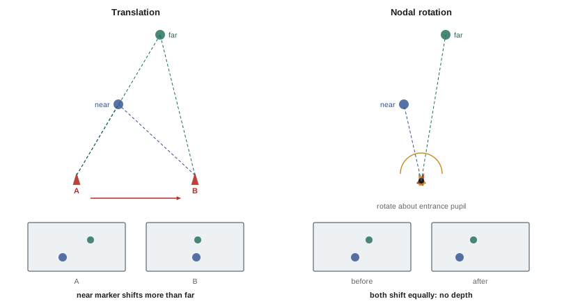
Parallax, the apparent relative motion of near and far objects as the camera moves, is what makes 3D tracking possible: by comparing how features at different depths shift, the software infers depth and camera position. A camera that only rotates around its entrance pupil (a nodal pan or tilt) produces no parallax, so it cannot be solved in 3D, but it does not need to be: the shot can be tracked as a rotation, and backgrounds can be placed as flat projections or panoramas, which is simpler and cheaper. Problems arise with moves that are nearly nodal but not quite, for example a tripod pan where the head's rotation point is behind the lens, producing small parallax that confuses solvers. Telling the VFX team whether a move was nodal, and using nodal heads when shooting backgrounds or tiles (Lesson 4), avoids this ambiguity. Long lenses and distant subjects also show little parallax, making solves harder; adding foreground markers or features helps.
What trackers need to see
Tracking software follows high-contrast, well-defined features: corners, edges, texture, small spots. It struggles with featureless areas such as clear skies, plain walls and large, evenly lit green screens; with motion blur that smears features; with reflections and specular highlights that move independently of surfaces; with heavy grain or noise; with shallow depth of field that blurs background features; and with objects moving within the scene, such as people and trees, which do not move with the camera. Good tracking footage contains plenty of static features at different depths, distributed across the frame, visible for many frames. Where the natural scene lacks such features, tracking markers are added.
Tracking markers
Tracking markers are small, high-contrast targets placed in the scene to give trackers reliable features. On green and blue screens, markers are typically crosses or dots in a contrasting but keyable color, such as a slightly different shade of the screen color, black, or white tape, sized so that they are clearly visible but easy to remove. On real sets and locations, markers may be dots of tape, small cones, tennis balls on stands, or purpose-made targets. Guidelines for placement include:
- Place markers at several depths: on the background screen, on the floor, and on stands at intermediate distances, to provide parallax.
- Distribute markers across the frame so that at least several (often eight or more) are visible in every frame of the shot, including when the camera moves.
- Avoid placing markers behind actors' heads and hair, where removal is difficult.
- Size markers so that they appear as several pixels across, without being so large that removing them is costly.
- Record marker positions with a survey or measurements where possible.
Markers must be removed in compositing, so placement is a balance between tracking needs and cleanup cost; discuss with the VFX supervisor.
Here \(W\) is the width of the frame at the screen distance \(d\) (from \(W = d \, w_s / f\)), and \(n_x\) is the number of markers wanted across the frame width; marker spacing should be no larger than \(s_{\max}\).
Worked problem
Spacing markers on a blue screen
A camera with a full-frame sensor (36 mm wide) and a 35 mm lens films an actor walking in front of a blue screen 8 m from the camera. The VFX supervisor wants at least four markers across the frame width and three down its height at all times, allowing for the camera to pan. How far apart should markers be on the screen?
Show solution
- Frame width at the screen: \(W = 8 \times 36 / 35 \approx 8.2\) m.
- Frame height (24 mm sensor height): \(H = 8 \times 24 / 35 \approx 5.5\) m.
- Horizontal spacing for at least four across: 8.2 / 4 ≈ 2.0 m; choose about 1.8 m to allow for edges and panning.
- Vertical spacing for three down: 5.5 / 3 ≈ 1.8 m; choose about 1.5 m.
Answer: Markers roughly 1.8 m apart horizontally and 1.5 m vertically, extended across the full area the camera may see.
Lens data and distortion
A camera solve depends on knowing the lens: its focal length, its distortion and, for zooms, how these change through the zoom range. Wide-angle lenses bend straight lines (barrel distortion), anamorphic lenses add complex distortion and squeeze, and many lenses breathe, changing field of view as focus changes (CINE-210). Matchmovers remove distortion before solving, then reapply it so that CG matches the plate. To do this accurately, they need lens grids: footage of a flat grid or checkerboard chart, shot square to the camera with every lens and focal length used, often at several focus distances. Smart lens systems, such as Cooke /i and ARRI LDS, record focal length, focus and iris for every frame, which greatly helps solving shots with focus pulls and zooms (Lesson 7). Without lens grids or metadata, matchmovers must estimate distortion from the footage itself, which is slower and less accurate.
| Data | Why matchmovers need it |
|---|---|
| Lens focal length and serial number | Field of view and lens-specific distortion |
| Lens grid for each lens | Measure and remove distortion |
| Focus distance and iris per frame | Breathing, depth of field and focus pulls |
| Sensor mode and dimensions | Field of view and image area |
| Camera height and tilt | Starting point for the solve |
| Survey or measurements of the set | Scale and placement of CG |
| Marker positions | Constraints for the solve |
Survey and scale
A camera solve on its own produces a camera path and point positions in arbitrary units and orientation. To place CG elements at the correct scale and position, matchmovers need real measurements: distances between markers, the height of the camera, the dimensions of the set, or a full survey made with a total station or LiDAR scanner (Lesson 7). Even simple tape measurements, recorded on a sketch, between a few key points improve solves dramatically. Shooting a reference frame with a measuring stick or a known-size object also helps.
Object, body and facial tracking
Some shots require tracking moving objects or performers rather than the camera: attaching CG armor to an actor, replacing a prop, adding digital makeup or tracking a vehicle for added damage. Object tracking uses features on the object itself; performers may wear small tracking markers on costumes or skin, or full motion capture suits in dedicated volumes. Facial tracking for digital makeup or face replacement uses dots on the face or markerless techniques with high-resolution footage. Witness cameras, additional cameras filming the action from other angles, provide extra viewpoints that help reconstruct motion in 3D (Lesson 7). These techniques should be planned with the VFX supervisor, since markers on actors affect makeup and costume schedules.
Real-time camera tracking on set
Virtual production stages and LED volumes use real-time camera tracking systems that report the camera's position and orientation to a game engine many times per second. Common technologies include optical systems that use infrared cameras to track reflective markers on the camera, and inside-out systems in which a sensor on the camera tracks markers or features on the ceiling or around the stage. Combined with lens encoders that report focus, iris and zoom, real-time tracking allows the engine to render the correct perspective on an LED wall (Lesson 10) or to produce a live composite for simulcam. Real-time data can also feed post-production, reducing matchmove work, though tracking accuracy and synchronization must be verified, since small errors are visible in final composites.
Shooting habits that help matchmove
Habits that help include keeping tracking features visible throughout the shot, avoiding unnecessary motion blur on VFX-heavy shots, recording lens and camera data for every take, shooting lens grids at the start or end of each lens use, noting whether moves were nodal, keeping the frame free of shaky handheld movement when it is not a creative choice, and leaving handles before and after the move. When a shot is planned with heavy camera movement through a sparse environment, such as a drone shot over open water, consider adding features to the scene or capturing additional data, since solving such shots can be extremely difficult.
Common reasons a track fails
Matchmovers most often struggle with shots where the camera moves but nothing in the frame shows that motion clearly. Examples include a moving camera against a blank, evenly lit green screen with too few markers; a long lens on a distant background with almost no parallax; heavy motion blur that smears features; very shallow depth of field, where most of the frame is soft; and shots where most visible features move, such as water, foliage in wind or crowds. Rolling-shutter skew in fast pans adds another complication. Each of these can be reduced at the shoot: add markers, include some foreground features, use a faster shutter where the look allows, record lens data and focus distance, and keep at least some static, textured detail visible throughout the shot.
Markers outdoors
On locations, markers may be small tennis balls on stands, crosses of tape on the ground, or high-contrast targets attached to walls or trees, chosen to be easy to remove. They should be placed at a range of depths, not all on one plane, because features at different distances give the solver the parallax it needs. Permission is needed before attaching anything to buildings or natural features, and all markers must be removed after the shoot.
Survey data
Survey data gives the solver real-world measurements to anchor the solve. A total station or laser measures the three-dimensional position of selected markers and set features relative to a known origin, and the matchmover uses these points to fix scale and orientation. Even a few accurately measured distances between markers, recorded with a tape, help confirm that the solved camera is at the correct height and distance.
Common mistakes
MistakePlain green screens with no markers on moving shots.
InsteadPlace markers at several depths and spacings.
MistakeMarkers behind actors' hair.
InsteadPlace markers where removal is easy.
MistakeNo lens grids for wide or anamorphic lenses.
InsteadShoot lens grids for each lens and focal length.
MistakeNearly nodal moves without notes.
InsteadUse nodal heads or document the move.
MistakeNo measurements of the set.
InsteadRecord distances, heights and surveys.
Summary and key terms
- Matchmoving reconstructs the real camera's motion and lens.
- 2D tracking suits flat or nodal shots; 3D solves need parallax.
- Trackers need static, high-contrast features at different depths.
- Tracking markers should be distributed, at several depths and easy to remove.
- Lens grids and smart lens metadata are essential for accurate solves.
- Surveys and measurements provide scale and placement.
- Real-time tracking drives LED volumes and simulcam.
- Matchmove
- Reconstruction of camera motion for VFX.
- Camera solve
- Computed 3D camera path from tracked features.
- 2D tracking
- Following features on the image plane.
- Reprojection error
- Pixel difference between tracked and predicted features.
- Parallax
- Relative motion of near and far objects as the camera moves.
- Nodal pan
- Rotation around the entrance pupil without parallax.
- Tracking marker
- High-contrast target placed to aid tracking.
- Lens grid
- Chart footage used to measure distortion.
- Survey
- Measured positions of points in a set.
- Witness camera
- Extra camera filming action from another angle.
Practice problems
Work each problem on paper first, then reveal the answer to check.
When is 2D tracking enough?
Show answer
Locked-off or nodal shots and flat replacements.
Why can a nodal pan not be solved in 3D?
Show answer
It has no parallax.
Name three things trackers struggle with.
Show answer
Featureless areas, motion blur, reflections, noise, moving objects.
Why place markers at several depths?
Show answer
To provide parallax.
Frame width at 10 m with a 50 mm lens on a 36 mm sensor?
Show answer
7.2 m.
Marker spacing for five across that width?
Show answer
About 1.4 m.
What is a lens grid for?
Show answer
Measuring and removing distortion.
What do smart lens systems record?
Show answer
Focal length, focus and iris per frame.
Why are survey measurements useful?
Show answer
They give scale and placement.
Name two real-time tracking technologies.
Show answer
Optical outside-in markers, inside-out ceiling markers.
Lesson quiz · 5 questions
Score 60% or more to complete this lesson.
Create a free account to save your progress, take quizzes and earn a certificate.