
CON-120 · Lesson 1 of 12 · 29 min
Why drawings matter and the drawing set
A building is described twice before anyone breaks ground: once in drawings and once in words. The drawings show where things go, what shape they are and how big they are; the specifications say what they are made of, how good they must be and how they must be installed. Together with the contract, they are the construction documents, and they are the single most important source of information on a construction project. Every estimate, schedule, purchase order, shop drawing, layout mark and inspection starts from them. A construction manager, superintendent, estimator or trade supervisor who cannot read drawings quickly and accurately cannot do the job. This course teaches you to read a full set of construction drawings: how they are organized, the conventions they use, how to scale and dimension from them, and what each discipline's sheets tell you, from the site plan to the electrical panel schedule. It finishes with the project manual, digital drawings and BIM, revisions and RFIs, and the as-built record. This first lesson explains why drawings matter, who produces them, how a drawing set is organized and how to find your way around one.
Drawings as a language
Construction drawings are a graphic language with its own vocabulary and grammar. The vocabulary is the set of line types, symbols, hatch patterns and abbreviations; the grammar is the system of views, scales, references and notes that ties them together. Like any language, it has dialects: each discipline uses its own symbols, each country and many owners have their own standards, and every design office has habits of its own. But the core grammar is remarkably consistent, so a person who learns to read one well-organized set can read most others after a few minutes of orientation.
Drawings are not pictures of the finished building. They are instructions, drawn to scale and annotated, telling a builder what to build. They simplify reality: a wall becomes two parallel lines with a hatch, a door becomes a line and an arc, a light fixture becomes a small circle with a letter beside it. They also show things you will never see in the finished building, such as reinforcing steel inside a concrete wall, the slope of a buried drain or the fire rating of a partition. Learning to read drawings means learning to imagine the three-dimensional object, its materials and its construction sequence from these abstractions.
Who produces the drawings
On a typical design-bid-build project, the owner hires an architect, who leads a team of engineering consultants. Each consultant produces drawings for its discipline, and the architect coordinates them into one set:
- Civil engineers: site grading, roads, parking, site services (water, sanitary and storm sewers) and erosion control.
- Landscape architects: planting, hardscape, site furniture and irrigation.
- Architects: building layout, walls, doors, windows, finishes, stairs, roofs, the building envelope and life safety plans.
- Structural engineers: foundations, structural framing, reinforcing, connections and loads.
- Mechanical engineers: heating, ventilation and air conditioning (HVAC), plumbing, drainage and often fire protection.
- Electrical engineers: power distribution, lighting, fire alarm, communications, security and other low-voltage systems.
- Specialist consultants: food service, elevators, acoustics, audio-visual, laboratories and others as the project requires.
On design-build and integrated projects the contractor may employ or partner with the designers, but the drawings serve the same purpose. Contractors and trades also produce drawings of their own: shop drawings that show exactly how a component will be fabricated and installed, coordination drawings that resolve conflicts between trades, and as-built drawings that record what was actually built (Lessons 11 and 12).
In the United States, architects and professional engineers are licensed by each state, and the drawings they issue for permit and construction carry their seal and signature. State licensing boards set rules about when a seal is required and what it means. A sealed drawing is a professional's statement of responsibility for the design.
Drawings in the contract
On most projects the drawings are contract documents. They define the scope of work the contractor has agreed to build for the contract price. That has important consequences:
- What is shown on the drawings (and described in the specifications) is in the contract; work not shown or described may be a change.
- Contracts usually say that the drawings and specifications are complementary: what is required by one is as binding as if required by both.
- Contracts usually establish an order of precedence for resolving conflicts between documents, and often say that figured dimensions govern over scaled measurements and that large-scale details govern over small-scale drawings.
- The contractor is usually required to review the documents and report errors, inconsistencies and omissions it discovers, but is not responsible for the design itself.
American standard contracts such as AIA Document A201 General Conditions of the Contract for Construction state that the contract documents are complementary and that what is required by one shall be as binding as if required by all. They require the contractor to study the documents and report errors, inconsistencies or omissions. Many projects add an order of precedence in the supplementary conditions or Division 01, and specifications commonly state that figured dimensions govern over scaled dimensions.
Because the drawings carry contractual weight, reading them carelessly is expensive. An estimator who misses a sheet underbids the job. A superintendent who builds from an outdated revision tears out work. A project manager who does not notice a conflict between the architectural and structural drawings discovers it when the steel arrives and does not fit.
The life of a drawing set
Drawings evolve through the design phases (CON-100 introduced the phases themselves). For the reader, what matters is that every set is issued for a purpose, and the purpose is printed on the sheets:
- Schematic design and design development sets show the design at increasing levels of detail; they are used for owner approvals, cost estimates and constructability reviews, not for building.
- Permit sets are issued to the authority having jurisdiction for building permit review.
- Tender or bid sets are issued for pricing; addenda issued during the tender period change them.
- Issued for construction (IFC) sets, sometimes called construction sets, are the drawings the work is built from, incorporating addenda.
- Revisions, supplemental instructions, change orders and RFI responses modify the IFC set during construction (Lesson 11).
- Record drawings and as-builts document the finished work (Lesson 12).
The single most important habit for anyone in the field is to check the issue status and revision of every sheet before using it. A drawing stamped "Not for construction" or "Preliminary" is not an instruction to build.
How a drawing set is organized
A large project may have hundreds of sheets, but they follow a predictable order. Most sets open with general sheets and then run discipline by discipline in roughly the order that work happens on site, from the ground up and from the structure out to the finishes and systems. A common order is:
| Discipline designator | Discipline | Typical contents |
|---|---|---|
| G | General | Cover sheet, sheet index, abbreviations, symbols legend, code summary |
| C | Civil | Site survey, grading, site services, erosion and sediment control |
| L | Landscape | Planting, hardscape, irrigation |
| A | Architectural | Plans, elevations, sections, details, schedules, finishes |
| S | Structural | General notes, foundation and framing plans, sections, details |
| F (or FP) | Fire protection | Sprinkler and standpipe layouts, risers |
| P | Plumbing | Domestic water, sanitary and storm drainage, fixtures |
| M | Mechanical | HVAC ductwork and piping, equipment schedules, controls |
| E | Electrical | Power, lighting, panel schedules, single-line diagram |
| T (or CS) | Telecommunications | Data, voice, security, audio-visual |
Within each discipline, sheets usually progress from general to specific: general notes and legends first, then plans, then elevations, then sections, then details and schedules. This structure lets you go quickly from the big picture to the exact information you need.
Sheet numbers
Every sheet has a unique number, and the number tells you where the sheet belongs. Systems vary, but a widely used pattern starts with a discipline letter followed by a sheet type digit and a sequence number. Under this pattern, A-101 might be the first architectural floor plan, A-201 an architectural elevation, A-301 a building section and A-501 a detail sheet. Other offices simply number A1, A2, A3 and so on. The cover sheet or sheet index always lists every sheet, its title and its current revision; it is the first thing to check when you receive a set.
In the United States, the National CAD Standard (NCS), published by the National Institute of Building Sciences with the AIA and CSI and now in Version 7, sets out discipline designators, sheet type designators and sheet numbering, drawing conventions, symbols and CAD layer names. Many firms and public owners follow it closely; others adapt it. Always read the sheet index and legend rather than assuming a system.
| Sheet type digit | Content |
|---|---|
| 0 | General: symbols, legends, notes |
| 1 | Plans (horizontal views) |
| 2 | Elevations (vertical views) |
| 3 | Sections |
| 4 | Large-scale views (enlarged plans, sections, elevations) |
| 5 | Details |
| 6 | Schedules and diagrams |
| 7 | User defined |
| 8 | User defined |
| 9 | 3-D representations |
The title block
Every sheet has a title block, usually along the right edge or bottom of the sheet. It is the sheet's identity card and contains:
- The project name, address and project number.
- The owner's name.
- The name and contact information of the firm that prepared the sheet, and often of the prime consultant.
- The professional seal or stamp of the responsible architect or engineer.
- The sheet title (for example, "Second Floor Plan") and sheet number.
- The scale or scales used, though many sheets say "as noted" because each view has its own scale.
- Drawn by, checked by and approved by initials, and the date.
- A revision block listing each revision number or letter, its date and a short description.
- The issue status, such as "Issued for Tender" or "Issued for Construction".
- A north arrow and a key plan on many plan sheets, showing which part of the building the sheet covers.
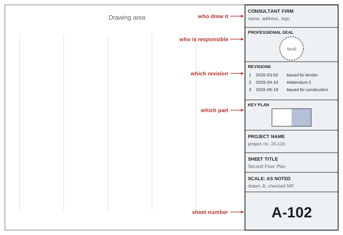
Experienced readers glance at the title block before anything else, asking: Is this the right project and building? Which revision is it, and is it current? Is it issued for construction? Which part of the building does it cover? What scale is it?
Finding your way around: references between sheets
No single sheet tells the whole story. A floor plan shows where a wall goes; a section shows how tall it is and how it meets the roof; a detail shows how its base is sealed. Drawings tie these together with reference symbols, or callouts, that point from one view to another. The most common are:
- Section cuts: a line through a plan or elevation with a symbol at each end, showing where an imaginary cut is taken and the direction of view. The symbol carries two pieces of information, usually the section number above a line and the sheet number where the section is drawn below it.
- Detail callouts: a circle or cloud around part of a view, with a bubble giving the detail number and sheet.
- Elevation markers: symbols on a plan showing the direction of view for exterior or interior elevations, again with view and sheet numbers.
- Grid lines: lettered and numbered lines that run across all plans and sections, giving every part of the building an address (Lesson 3).
- Tags: symbols with letters or numbers that identify doors, windows, walls, equipment and fixtures and link them to schedules (Lessons 6, 8 and 9).
Worked problem
Reading a section callout
On architectural plan A-102 you find a section cut through an exterior wall. The bubble at the end of the cut line reads 3 above a horizontal line and A-301 below it, and the solid triangle on the bubble points north. What does the symbol tell you, and where do you look?
Show solution
- The number above the line, 3, is the view number: the section is view 3 on its sheet.
- The number below the line, A-301, is the sheet on which the section is drawn. Under the sheet type convention, the 3 in A-301 indicates a section sheet, which is consistent.
- The triangle shows the direction of view: you are looking north at the cut wall, so north is "into" the section and the left side of the section is west.
- Turn to sheet A-301 and find the view labeled 3. Its title will usually repeat the reference and name the view, such as "Wall Section", with its scale.
Answer: The symbol refers to section 3 drawn on sheet A-301, looking north. Turn to A-301, view 3, to see the full construction of that wall.
Following callouts back and forth is how professionals read drawings. A useful habit is to keep a finger (or a bookmark in a PDF) on the plan while you check the section and detail it refers to, then return to the plan. With practice, you build a three-dimensional understanding of each part of the building.
Sheet sizes and printing
Drawing sheets come in standard sizes. Most drawings are now viewed on screens and tablets, but sheet size still matters because scales are set for a full-size print and because half-size prints are common on site.
American projects use ARCH sheet sizes, most commonly ARCH D (24 × 36 in) and ARCH E1 (30 × 42 in) or ARCH E (36 × 48 in) for full-size drawings. ANSI sizes such as ANSI D (22 × 34 in) are also used, especially for civil and engineering drawings, and 11 × 17 in (ANSI B, or tabloid) is common for reduced sets.
A drawing printed at half size is no longer at the scale written on it: a 1:100 drawing becomes 1:200, and a 1/4 in = 1 ft drawing becomes 1/8 in = 1 ft. This is a common source of errors on site, and one reason why good drawings include graphic scale bars that shrink with the drawing (Lesson 3).
Drawings and the rest of the construction documents
Drawings rarely stand alone. They are interpreted alongside:
- The specifications in the project manual, which describe materials, products, quality and workmanship (Lesson 10).
- The contract agreement and general and supplementary conditions, which set out roles, responsibilities, payment and changes.
- Addenda issued during tendering, which modify the drawings and specifications before the contract is signed.
- Geotechnical reports, surveys, hazardous materials reports and other reference documents, which may or may not be contract documents depending on the contract.
A simple rule of thumb: drawings show quantity, location, size and relationships; specifications describe quality, products and methods. When the drawings say "concrete wall", the specifications say what strength, exposure class, cement type, finish and curing that concrete must have.
A first look at a new set
When a new set lands on your desk or tablet, a systematic first pass saves time later. Professionals typically:
- Read the cover sheet and sheet index; confirm the set is complete and note the issue date and status.
- Read the general sheets: abbreviations, symbols legend, general notes and code summary.
- Flip through the architectural plans to understand the building's size, shape, number of stories and main spaces.
- Look at the elevations and building sections to understand the height, the envelope and the roof.
- Skim the structural general notes and foundation and framing plans to understand the structural system.
- Skim the mechanical, plumbing, fire protection and electrical plans to understand the systems and where major equipment sits.
- Note questions, apparent conflicts and missing information as you go.
This first pass might take an hour on a mid-sized project. It gives you a mental model of the building that makes every later, more detailed reading faster and more accurate.
Common mistakes
MistakeBuilding from a sheet without checking its revision and issue status.
InsteadCheck the title block and sheet index before using any sheet.
MistakeTreating drawings as pictures rather than instructions.
InsteadRead the notes, references and tags that give every line its meaning.
MistakeReading one discipline in isolation.
InsteadCross-check architectural, structural and MEP sheets for the same area.
MistakeAssuming every firm uses the same sheet numbering and symbols.
InsteadRead the sheet index, legends and abbreviations for each set.
MistakeIgnoring the specifications because the drawings seem clear.
InsteadRead drawings and specifications together; they are complementary.
Summary and key terms
- Drawings show location, size, shape and relationships; specifications describe quality and methods.
- Each discipline produces its own sheets, coordinated by the prime consultant.
- Drawings are contract documents, so precedence rules and careful reading matter.
- Every set is issued for a purpose; only issued-for-construction sheets are built from.
- Sets run by discipline, and within each discipline from general to specific.
- The title block identifies the project, sheet, scale, revision and issue status.
- Callouts, grids and tags link plans, sections, details and schedules.
- Construction documents
- The drawings, specifications and contract that define the work.
- Drawing set
- All the sheets for a project, organized by discipline.
- Discipline designator
- Letter identifying a sheet's discipline, such as A or S.
- Title block
- Area of a sheet identifying project, sheet, scale and revisions.
- Sheet index
- List of all sheets with titles and current revisions.
- Callout
- Symbol referring from one view to another view or sheet.
- Section cut
- Line showing where an imaginary vertical cut is taken.
- Issued for construction
- Status of drawings released for building the work.
- Shop drawing
- Fabricator's drawing showing how a component will be made and installed.
- Key plan
- Small plan showing which part of a building a sheet covers.
Practice problems
Work each problem on paper first, then reveal the answer to check.
Name three things drawings show and one thing specifications describe.
Show answer
Location, size, shape, relationships; quality, products, methods.
Which discipline letter usually precedes structural sheets?
Show answer
A (architectural).
What does the 2 in A-201 usually indicate?
Show answer
An elevation sheet.
What are the first two things to check in a title block?
Show answer
The revision and the issue status (and that it is the right project and sheet).
A section bubble reads 5 over S-302. What does it mean?
Show answer
Section 5 is drawn on sheet S-302.
Why are large-scale details usually given precedence over small-scale plans?
Show answer
They show more precise, specific information.
What happens to a 1:50 drawing printed at half size?
Show answer
It becomes 1:100.
Who usually produces shop drawings?
Show answer
Fabricators, suppliers or trade contractors.
What is a key plan?
Show answer
A small plan showing which part of the building the sheet covers.
List four steps in a first pass through a new set.
Show answer
Index, general sheets, architectural plans, elevations and sections, structural, MEP, note questions.
Lesson quiz · 5 questions
Score 60% or more to complete this lesson.
Create a free account to save your progress, take quizzes and earn a certificate.