
CON-120 · Lesson 6 of 12 · 28 min
Architectural drawings and schedules
The architectural drawings are the heart of most building sets. They define the building's layout, its walls, doors and windows, its envelope, its stairs and vertical circulation, its finishes and its life safety features, and they coordinate the work of every other discipline. They are also the largest part of most sets, with floor plans, enlarged plans, reflected ceiling plans, roof plans, elevations, sections, details and many schedules. This lesson walks through the architectural sheets in the order you will meet them, explains what each contains and how to read it, and spends time on the schedules and legends, the tables where much of the real information lives: door, window, room finish and partition type schedules.
The architectural general sheets
Architectural sheets usually open with general information: the architectural abbreviations, symbols and material legends, general notes, and often a code analysis or life safety summary. The code summary lists the governing building code and edition, the building's occupancy classification, construction type, building area and height, occupant loads, required fire separations and fire-resistance ratings, sprinkler status and exit requirements (CON-130 and CON-140 cover the codes themselves). For the reader, the code summary explains why walls have particular ratings and why doors have particular hardware and labels.
Many sets also include life safety or code plans: simplified floor plans showing fire separations and fire walls with their ratings, exit routes, travel distances, occupant loads for each space and the locations of fire extinguishers and fire alarm devices. These plans are an efficient way to understand the building's fire strategy and to see which walls, doors and penetrations need special care.
Floor plans
Architectural floor plans show, for each story:
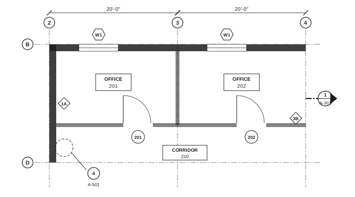
- Exterior walls, interior partitions, columns and shafts, with wall type tags.
- Doors with their swings and door tags; windows with window tags.
- Room names and numbers, sometimes with areas.
- Stairs with their direction of travel (usually an arrow labeled UP or DN from the floor shown), number of risers and landings; elevators and escalators.
- Built-in items such as counters, cabinets, washroom fixtures and partitions.
- Grid lines and dimensions locating walls, openings and features.
- References to elevations, sections, details and enlarged plans.
- Keynotes and notes on specific items.
Overall plans of large buildings are often drawn at 1:200 or 1:100 (1/16" or 1/8" = 1'-0") and split into parts on separate sheets, with a key plan and match lines. Dimensioned plans at 1:100 or 1:50 (1/8" or 1/4" = 1'-0") give the layout information, and enlarged plans at 1:50 or 1:25 cover complex areas.
Partition types and wall assemblies
Rather than draw every wall in full, architects define wall types in a legend: a set of small sections, each showing a wall assembly with its tag, construction and properties. A typical partition type legend shows for each type:
- The layers: stud size and spacing, number and type of gypsum board layers on each side, insulation, and finishes.
- The height: to the underside of the ceiling, to the ceiling plus a short distance, or to the underside of the structure above ("to deck").
- The fire-resistance rating, if any, with a reference to the tested or listed assembly that achieves it.
- The acoustic rating, usually a sound transmission class (STC) value.
- Special notes, such as "seal top and bottom with acoustic sealant" or "provide deflection track at head".
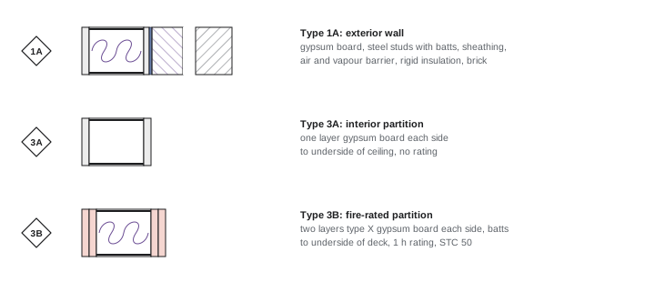
Rated walls are among the most important items to read correctly. A fire-rated partition must use the exact tested assembly, run to the structure above, have its joints and head sealed with listed systems, and have every penetration by pipes, ducts and cables firestopped. Doors in rated walls need rated frames and doors with labels, and ducts need fire dampers. Construction managers often highlight rated walls on the plans in color to make sure every trade knows where they are.
In the United States, fire-resistance ratings for walls and floors are established by testing to ASTM E119 or UL 263, with firestop systems tested to ASTM E814 or UL 1479. Drawings commonly reference a UL design number (such as U419) or a Gypsum Association (GA-600) file number for each rated wall type.
Doors and the door schedule
Doors are tagged on plans and described in a door schedule, a table that typically lists for each door:
- Door number, usually linked to the room number.
- Size: width, height and thickness.
- Door type (referring to door type elevations showing flush, glazed, louvred or other designs) and material, such as hollow metal, wood or aluminum.
- Frame type (referring to frame elevations) and material.
- Fire rating, such as 20, 45, 60 or 90 minutes, with a required label.
- Hardware set number, referring to hardware groups in the specifications that list hinges, locks, closers, exit devices, stops and seals.
- Glazing type, finish, head, jamb and sill details, and remarks such as "card reader", "automatic operator" or "acoustic seals".
| Door | Size (W × H) | Door type / material | Frame | Rating | Hardware set | Remarks |
|---|---|---|---|---|---|---|
| 201 | 3'-0" × 7'-0" | A / WD | F1 / HM | — | 04 | Office lock |
| 202 | 3'-0" × 7'-0" | A / WD | F1 / HM | — | 04 | Office lock |
| 210A | 2 @ 3'-0" × 7'-0" | C / HM | F3 / HM | 45 min | 12 | Pair, hold-open on fire alarm release |
| 215 | 3'-6" × 7'-0" | B / WD | F2 / HM | 20 min | 08 | Vision panel, closer, accessible |
Worked problem
Reading a door schedule
Using the door schedule excerpt above, describe door 210A and list what must be checked when ordering and installing it.
Show solution
- Door 210A is a pair of doors, each the stated width and height, so the frame opening is two leaves wide.
- Door type C, hollow metal, refers to a door type elevation; check it for vision panels or louvers. Frame type F3 refers to a frame elevation; check for sidelights or transoms.
- The 45-minute rating means both doors and the frame must carry fire labels for that rating, glazing (if any) must be fire-rated, and the wall it sits in should be a rated assembly; check the partition type on the plan.
- Hardware set 12 in the specifications lists the hardware; for a rated pair it will include closers, positive latching (often with a coordinator and flush bolts or vertical rod exit devices) and possibly hold-open devices released by the fire alarm, as the remark notes.
- The fire alarm release requires coordination with the electrical drawings for power and alarm connections.
Answer: A rated 45-minute pair of hollow metal doors in a hollow metal frame, with hardware set 12 and fire alarm-released hold-opens. Check door and frame type elevations, labels, the wall rating, the hardware set and electrical coordination before ordering.
Door schedules drive large purchase orders, long lead times and many coordination items. Hardware in particular involves the architect, the hardware consultant, the door supplier, the electrical contractor (for electrified hardware and access control) and the owner's security team.
Windows, curtain wall and storefront
Windows are tagged by type rather than individually, and each type is shown in a window type schedule or legend with an elevation of the unit showing its overall size, operable and fixed panels, mullion layout and glazing types. Notes and the specifications give frame materials, glazing performance (U-value or thermal transmittance, solar heat gain, visible transmittance), safety glazing locations and testing requirements. Curtain wall and storefront systems are usually shown in large-scale elevations with typical mullion details, and the detailed engineering is done by the supplier in shop drawings.
A key distinction is between the nominal window size, the actual unit size and the rough opening into which the unit is installed. Schedules should state which they give, and the rough opening must allow for shims, insulation, sealant and flashing. Window sizes and sill heights must also be checked against the exterior elevations, the floor plans and the structural openings.
Room finish schedules
Finishes are usually given in a room finish schedule, listing for each room the floor finish and base, wall finishes (sometimes by wall: north, east, south, west), ceiling type and height, and remarks. Finish codes, such as CPT-1 for a carpet type or PT-2 for a paint color, refer to a finish legend and the specifications. Some projects use finish plans instead of or in addition to schedules, shading or hatching floor areas by finish type and tagging walls.
| Room | Name | Floor | Base | Walls | Ceiling | Ceiling height |
|---|---|---|---|---|---|---|
| 201 | Office | CPT-1 | RB-1 | PT-1 | ACT-1 | 9'-0" |
| 210 | Corridor | LVT-1 | RB-1 | PT-2 | ACT-1 | 8'-6" |
| 212 | Washroom | PT-T1 | CB-1 | WT-1 to 2 100, PT-3 above | GB-1 (painted) | 8'-0" |
Worked problem
A finish quantity from a schedule
Office 201 measures 14'-0" by 12'-0" inside finished walls and has a ceiling height of 9'-0". It has one door 3'-0" × 7'-0" and one window 6'-0" × 5'-0". The schedule calls for PT-1 on the walls. Estimate the paintable wall area, and the floor area of carpet CPT-1.
Show solution
- Perimeter: 2 × (14 + 12) = 52 ft.
- Gross wall area: 52 × 9 = 468 ft².
- Openings: door 3 × 7 = 21 ft²; window 6 × 5 = 30 ft²; total 51 ft².
- Net paintable area: 468 − 51 = 417 ft² (per coat).
- Carpet: 14 × 12 = 168 ft² net, about 18.7 yd², before waste allowance.
Answer: About 417 ft² of wall paint per coat and 168 ft² (about 18.7 yd²) of carpet before waste. Estimators apply waste factors and follow the measurement rules of their firm or of standard methods (CON-200).
Reflected ceiling plans
Reflected ceiling plans (Lesson 4) show ceiling types, often by hatch or grid pattern, with ceiling heights noted in each room. Acoustic tile grids are drawn to show their layout and starting point, usually centered in the room so that border tiles are equal. RCPs also locate light fixtures, diffusers and grilles, sprinkler heads, speakers, smoke detectors, access panels and bulkheads, coordinated with the electrical and mechanical drawings. Because so many trades put something in the ceiling, the RCP is a key coordination drawing, and differences between it and the engineering drawings should be resolved before installation.
Exterior elevations and the building envelope
Exterior elevations show the building's faces with their materials, usually indicated by hatch and keynote: brick, metal panel, curtain wall, precast concrete, stucco or siding. They show window and door openings with their tags, control and expansion joints, louvers, canopies, signage and rooftop screens, and level markers for each floor and roof. Wall sections and envelope details then show the layers: cladding, air space or drainage cavity, insulation, the air barrier and vapor control layer, sheathing, studs or backup wall and interior finishes. Envelope details at windows, parapets, slab edges, penetrations and transitions between systems are where most leaks and failures start, so they deserve careful reading (CON-111 covers envelope construction).
Interior elevations and mounting heights
Interior elevations show walls with millwork, fixtures and accessories, and they give mounting heights: the heights of counters, sinks, mirrors, grab bars, switches, receptacles, dispensers, signs and other items. In washrooms, accessible counters and fixtures must meet specific dimensions, and the interior elevations, enlarged plans and accessibility details must be followed precisely.
In the United States, accessibility requirements come from the 2010 ADA Standards for Accessible Design, which apply to public accommodations and government facilities, and from building codes that reference ICC A117.1, Accessible and Usable Buildings and Facilities. Federal facilities may follow the Architectural Barriers Act standards.
Stairs, ramps and vertical circulation
Stairs appear on plans with an arrow showing the direction of travel and a note such as "18 R UP" (18 risers up). Enlarged stair plans and sections give the riser height, tread depth, landing sizes, handrail and guard heights, and nosing details. Codes limit maximum riser height and minimum tread depth, so the number of risers between two floors is calculated from the floor-to-floor height: for example, a floor-to-floor height of 3 600 mm divided into 20 risers gives 180 mm risers. Elevator shafts are shown with their pit depths, overrun heights and door locations, which must match the elevator supplier's requirements.
Roof plans
Roof plans show the roof from above: slopes and the direction of drainage (with arrows and percentages), high and low points, drains and scuppers, crickets that divert water around curbs, roof hatches and access, parapets and expansion joints, rooftop mechanical equipment on curbs or dunnage, and the locations of penetrations. Low-slope roofs are rarely truly flat; they slope to drains through sloped structure or tapered insulation, and the roof plan shows the layout. Comparing the roof plan with the structural framing plan and the mechanical roof plan is essential, because equipment loads, openings and curbs all affect the structure.
Common mistakes
MistakeTreating every wall as the same construction.
InsteadLook up every wall type tag, especially rated walls.
MistakeOrdering doors without checking hardware sets and labels.
InsteadRead the door schedule, door and frame types and hardware groups together.
MistakeConfusing window unit size with rough opening.
InsteadCheck what the schedule gives and allow for installation clearances.
MistakeIgnoring mounting heights on interior elevations.
InsteadFollow dimensions and accessibility requirements exactly.
MistakeReading the RCP without the electrical and mechanical plans.
InsteadCoordinate all ceiling devices before installation.
Summary and key terms
- Architectural general sheets include legends, notes and a code summary.
- Floor plans show walls, openings, rooms, stairs, dimensions and references.
- Partition type legends define wall assemblies, heights and fire and acoustic ratings.
- Door schedules give sizes, types, frames, ratings and hardware sets.
- Window schedules show unit types; check nominal, unit and rough opening sizes.
- Room finish schedules and RCPs define finishes, ceilings and ceiling devices.
- Elevations, interior elevations, stair and roof plans complete the picture.
- Code summary
- Table of code classification, ratings and life safety data.
- Life safety plan
- Plan showing fire separations, exits and travel distances.
- Partition type
- Defined wall assembly referenced by a tag.
- Fire-resistance rating
- Time an assembly resists a standard fire test.
- STC
- Sound transmission class: a wall's airborne sound rating.
- Door schedule
- Table of door sizes, types, frames, ratings and hardware.
- Hardware set
- Group of hardware items specified for a door.
- Rough opening
- Framed opening into which a unit is installed.
- Room finish schedule
- Table of floor, base, wall and ceiling finishes by room.
- Mounting height
- Specified height of a fixture or device.
Practice problems
Work each problem on paper first, then reveal the answer to check.
Where would you find a building's occupancy classification on the drawings?
Show answer
In the code summary on the architectural general sheets.
What does "18 R UP" on a stair mean?
Show answer
18 risers up from the floor shown.
Name three things a partition type legend shows.
Show answer
Layers, height, fire rating, STC, special notes.
Why must rated walls run to the structure above?
Show answer
To maintain the fire separation.
What does a hardware set number refer to?
Show answer
A group of hardware items in the specifications.
What is a rough opening?
Show answer
The framed opening into which a unit is installed.
A room is 5 m × 4 m with 2.6 m ceilings and 5 m² of openings. Net wall area?
Show answer
41.8 m².
What does an RCP coordinate?
Show answer
Ceilings, lights, diffusers, sprinklers, detectors and access panels.
Floor-to-floor 3 360 mm with 21 risers. Riser height?
Show answer
160 mm.
Why compare the roof plan with the structural framing plan?
Show answer
Equipment loads, openings and curbs affect structure.
Lesson quiz · 5 questions
Score 60% or more to complete this lesson.
Create a free account to save your progress, take quizzes and earn a certificate.