
CON-120 · Lesson 4 of 12 · 26 min
Orthographic projection: plans, elevations, sections and details
A building is three-dimensional; a sheet of paper is flat. Construction drawings solve this problem with orthographic projection: a set of flat views, each looking straight at the building from one direction, with every line drawn true to scale. A plan looks down, an elevation looks sideways, and a section looks at a slice. None of them alone describes the building, but together they do, and the reader's job is to combine them mentally into a three-dimensional understanding. This lesson explains how orthographic views are made, the main view types used in construction (plans, reflected ceiling plans, elevations, sections, enlarged views and details), how they relate to each other, and how pictorial views and 3-D models supplement them.
The idea of orthographic projection
Imagine a building placed inside a glass box. Looking straight at each face of the box, perpendicular to it, you trace what you see onto the glass. Every line is projected straight onto the glass, so lengths parallel to the glass appear at their true length and true shape, with no perspective. When the box is unfolded flat, the traced views line up with each other: the front view sits below the top view, and the side views sit beside the front view, sharing heights.
Construction drawings use this system, though views are placed on separate sheets rather than in one unfolded layout. The key properties are:
- Each view shows two of the three dimensions at true scale: a plan shows length and width, an elevation length and height, a section the same as an elevation but through the building.
- Surfaces that are parallel to the viewing plane appear at true shape; surfaces at an angle appear foreshortened, and surfaces perpendicular to it appear as lines.
- Views share dimensions: the length of a building on its plan equals its length on the front elevation, and heights on the front and side elevations match.
- Hidden edges can be shown with dashed lines, though construction drawings use them sparingly.
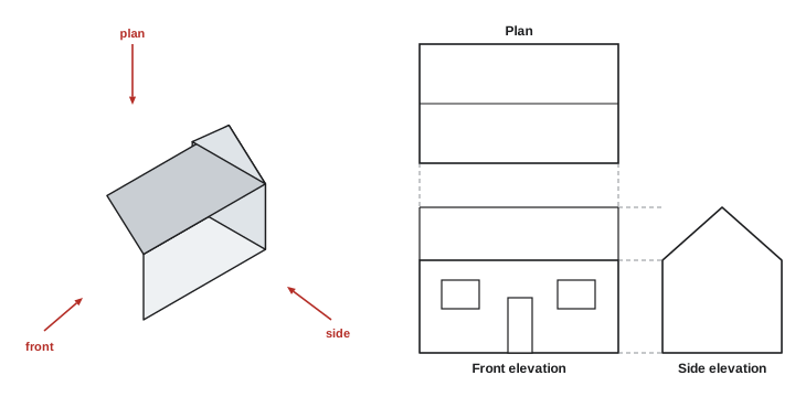
Reading orthographic drawings is a skill of visualization. Beginners often find it helpful to sketch a quick 3-D view from the plans and elevations, or to look at the 3-D model when one is available, until the habit of combining views becomes automatic.
Plans
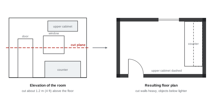
A floor plan is a horizontal section: imagine slicing through the building horizontally, usually about 1.2 m (4 ft) above the floor, removing the top half and looking down. Everything cut by the slicing plane, such as walls, columns, doors and windows, is drawn with heavy lines. Everything below the plane and visible, such as floor finishes, stairs, countertops and fixtures, is drawn with lighter lines. Important things above the plane, such as upper cabinets, bulkheads, skylights or the roof overhang, may be shown dashed.
Because the cut is taken at about counter height, a floor plan shows doors (with their swing arcs), windows (as thin lines within the wall thickness), and openings clearly. High windows above the cut plane may be shown dashed with a note giving their sill height.
Projects include many kinds of plans, each serving a purpose:
- Site plans: the building in relation to property lines, roads, parking, grading and services (Lesson 5).
- Foundation plans: footings, foundation walls, piles and grade beams (Lesson 7).
- Floor plans: the layout of each story, with walls, doors, windows, rooms and dimensions (Lesson 6).
- Framing plans: beams, joists, columns and bracing for each floor and the roof (Lesson 7).
- Roof plans: roof slopes, drains, curbs, equipment, parapets and penetrations, viewed from above.
- Reflected ceiling plans (RCPs): the ceiling of each floor, drawn as if reflected in a mirror on the floor, so that the plan has the same orientation as the floor plan below. RCPs show ceiling types and heights, bulkheads, lights, diffusers, sprinklers and access panels.
- Enlarged plans: washrooms, stairs, kitchens, elevator lobbies and other complex areas at a larger scale.
- Finish plans, furniture plans, life safety or code plans, and discipline plans for mechanical, plumbing, fire protection and electrical work (Lessons 8 and 9).
Reflected ceiling plans deserve a special note. If you looked up at a ceiling from below and drew it, it would appear mirror-reversed compared with the floor plan. Drawing it "reflected" avoids that, so that a light fixture shown at the north-east corner of the RCP is at the north-east corner of the room.
Elevations
An elevation is a view looking horizontally at a vertical face, without cutting through the building. There are two main kinds:
- Exterior elevations show each face of the building: its overall height, floor levels, roof profile, window and door openings, cladding materials and their joints, and exterior features such as canopies, louvers and signs. They are usually named by compass direction, such as "North Elevation", meaning the face of the building that faces north (you look south to see it), though some offices name them by the direction you look, which is why the elevation markers on the plan must be checked.
- Interior elevations show the walls of rooms, especially rooms with built-in elements such as kitchens, washrooms, laboratories and classrooms. They show cabinets, counters, fixtures, mirrors, grab bars, wall finishes and the heights of devices such as switches, receptacles and dispensers.
Elevations show heights clearly. Level markers on the side of an exterior elevation give the elevations of each floor, roof, parapet and top of wall, and dimensions or notes give the heights of window sills and heads. Because elevations do not cut through the building, they show surfaces and materials rather than construction.
Worked problem
Combining plan and elevation
On the second floor plan, window W3 is centered in the wall between grids 2 and 3, which are 24'-0" apart. The window schedule gives W3 as 8'-0" wide by 5'-0" high. On the south elevation, the second floor level marker reads 114'-0", and a note gives the window sill at 3'-0" above finished floor. Find the distance from grid 2 to each side of the window, and the elevations of the sill and head.
Show solution
- The bay center is 24'-0" ÷ 2 = 12'-0" from grid 2.
- The window extends 8'-0" ÷ 2 = 4'-0" either side of the center, so its sides are at 8'-0" and 16'-0" from grid 2.
- Sill elevation = floor elevation + sill height = 114'-0" + 3'-0" = 117'-0".
- Head elevation = sill + window height = 117'-0" + 5'-0" = 122'-0".
Answer: The window sides are 8'-0" and 16'-0" from grid 2; the sill is at 117'-0" and the head at 122'-0". Window schedule sizes may be nominal or rough opening sizes, so check the schedule notes before setting out.
Sections
A section is a vertical slice through the building or part of it, viewed in the direction shown by the section symbol on the plan. Everything cut by the slice is drawn heavy and hatched to show its material; things beyond the cut are drawn lighter. Sections are the views that show how a building is put together vertically: how the foundation supports the walls, how floors and roofs span, how the envelope layers are arranged, and how spaces relate in height.
Sections come at several scales:
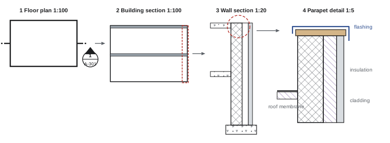
- Building sections cut through the whole building, typically at 1:100 or 1:50 (1/8" or 1/4" = 1'-0"). They show floor-to-floor heights, ceiling heights, roof slopes, stairs and the relationships between spaces.
- Wall sections cut through an exterior wall from foundation to roof, typically at 1:20 or 1:25 (3/4" or 1" = 1'-0"). They show every layer of the envelope, the floor and roof connections and key heights, and they refer to details at each junction.
- Detail sections cut through a small area, such as a window head, a parapet or a slab edge, at large scales such as 1:5 or 1:10 (3" or 1 1/2" = 1'-0").
Sections are where many construction questions are answered and many errors are found. Comparing a wall section with the structural drawings, the window shop drawings and the mechanical drawings for the same location often reveals conflicts, such as a duct that will not fit in the ceiling space or a beam that is deeper than the architect assumed.
Details
Details are large-scale drawings of specific conditions: how materials meet, how components are fastened, how water is shed and air sealed, how a handrail is anchored. They may be sections, plans or elevations at large scale, or pictorial views. Details resolve what smaller-scale drawings cannot show.
Details are usually collected on detail sheets (A-500 series under the common numbering) and referenced from plans, elevations and sections. Many details are typical, applying wherever the condition occurs; others are specific to one location. Some come from the designer's office library and may need adjustment for the project, so check that a typical detail really fits each place it is used. When a condition on the plans has no detail and is not obviously covered by a typical one, that is a question to ask.
How views relate
Professionals read drawings by moving between views. A typical sequence when studying part of a building is:
- Locate the area on the floor plan by grid and room number.
- Find the exterior or interior elevation of that wall to see openings, materials and heights.
- Follow the section cut to the building section and wall section to see the construction.
- Follow detail callouts to the large-scale details for each junction.
- Cross-check the structural, mechanical, plumbing and electrical drawings for the same grid area.
Remember that drawings at different scales show different amounts of information. A 1:100 plan might show an exterior wall as two lines with a hatch; the 1:20 wall section shows each layer; the 1:5 detail shows every fastener and sealant joint. Where they seem to differ, the larger-scale view normally governs, but a genuine conflict should still be resolved with the designer.
Pictorial views and 3-D
Orthographic views are precise but abstract. Pictorial views help people visualize:
- Isometric and axonometric views show three faces of an object at once, with parallel lines kept parallel and lengths measurable along the axes. Plumbing riser diagrams and some details use isometric views.
- Perspective views show the building as the eye sees it, with lines converging to vanishing points. They are used in presentations and marketing, not for construction.
- 3-D model views and exploded axonometrics are increasingly included in construction sets, especially for complex junctions, prefabricated assemblies and sequencing, and BIM models can be viewed directly (Lesson 11).
Pictorial views are excellent for understanding, but dimensions should always be taken from the orthographic drawings, where lengths are true and stated.
Schedules and diagrams
Not all information is best drawn. Schedules are tables that list items such as doors, windows, rooms and finishes, equipment, fixtures and panels, with their sizes, types, materials and other properties, linked to the drawings by tags (Lessons 6, 8 and 9). Diagrams show relationships without scale or exact location, such as electrical single-line diagrams, plumbing riser diagrams and control sequences. Both are part of the drawing set and carry the same contractual weight as the plans.
Building a mental model
The goal of reading orthographic drawings is a mental model: a three-dimensional picture of the building and how it is built, detailed enough to plan work, foresee problems and explain them to others. Techniques that help include:
- Sketching: a quick freehand isometric sketch of a tricky junction often clarifies it.
- Highlighting: marking different systems or materials on a printed or PDF sheet.
- Walking the drawings: mentally walking through the building from the entrance, room by room, checking what you would see.
- Comparing with the model: when a BIM model is available, using it to check your understanding, while remembering that the issued drawings are usually the contract documents.
- Visiting similar buildings: seeing how real construction matches drawn details builds intuition.
Common mistakes
MistakeReading a single view and assuming the rest.
InsteadCombine plan, elevation, section and detail for every area.
MistakeReading a reflected ceiling plan as if looking up.
InsteadRemember RCPs share the orientation of the floor plan.
MistakeConfusing which way an elevation is named.
InsteadCheck the elevation markers on the plan.
MistakeTaking dimensions from perspective or isometric views.
InsteadUse orthographic views with stated dimensions.
MistakeAssuming a typical detail fits every location.
InsteadCheck each condition and ask when it differs.
Summary and key terms
- Orthographic projection shows each face straight on, so lengths parallel to the view are true.
- A floor plan is a horizontal section cut about 1.2 m (4 ft) above the floor.
- Reflected ceiling plans share the orientation of the floor plan below.
- Elevations show faces and heights; sections cut through to show construction.
- Building sections, wall sections and details show increasing detail at larger scales.
- Callouts link views; larger-scale views normally govern where views differ.
- Pictorial and 3-D views aid understanding, but dimensions come from orthographic views.
- Orthographic projection
- Drawing views perpendicular to each face, at true scale.
- Floor plan
- Horizontal section through a story viewed from above.
- Reflected ceiling plan
- Ceiling plan drawn as if reflected onto the floor.
- Elevation (view)
- Horizontal view of a vertical face without cutting.
- Building section
- Vertical cut through the whole building.
- Wall section
- Vertical cut through a wall from foundation to roof.
- Detail
- Large-scale drawing of a specific condition.
- Isometric view
- Pictorial view showing three faces with equal axis scales.
- Cut plane
- Imaginary plane where a plan or section is taken.
- Enlarged plan
- Part of a plan redrawn at a larger scale.
Practice problems
Work each problem on paper first, then reveal the answer to check.
At about what height is a floor plan cut?
Show answer
About 1.2 m (4 ft) above the floor.
How are objects above the cut plane usually shown on a plan?
Show answer
Dashed.
What does a reflected ceiling plan show?
Show answer
Ceiling types, heights, lights, diffusers and sprinklers, oriented like the floor plan.
What two dimensions does an elevation show at true scale?
Show answer
Length and height.
What is the main difference between an elevation and a section?
Show answer
A section cuts through the building.
Floor at 103.000, sill 1.050 above floor, window 1.200 high. Head elevation?
Show answer
105.250.
At what scale are wall sections commonly drawn?
Show answer
1:20 or 1:25 (3/4" or 1" = 1'-0").
Which view generally governs where two views differ?
Show answer
The larger-scale view.
Name one use of isometric views in construction drawings.
Show answer
Plumbing riser diagrams or complex details.
List the views you would check to understand a window head.
Show answer
Plan, elevation, wall section, detail, window schedule.
Lesson quiz · 5 questions
Score 60% or more to complete this lesson.
Create a free account to save your progress, take quizzes and earn a certificate.