
ELE-202 · Lesson 11 of 12 · 31 min
Power, efficiency and DC power systems
Circuit analysis is often taught as a way of finding voltages and currents, but in practice the question is frequently about power: how much reaches the load, how much is wasted as heat, and how to deliver large amounts of it efficiently. This lesson applies the tools of the course to DC power systems. We distinguish maximum power transfer from maximum efficiency, model batteries and their internal resistance, see why data centers are moving to higher distribution voltages inside the rack, compare linear and switching regulators, and combine the efficiencies of a chain of converters into the figure that decides an electricity bill.
Maximum power or maximum efficiency?
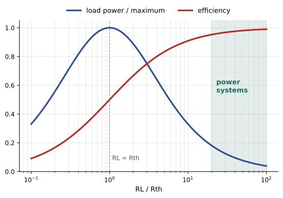
Lesson 6 showed that a source with Thévenin equivalent \(V_{th}\), \(R_{th}\) delivers maximum power to a load when \(R_{L} = R_{th}\). The efficiency of power delivery, the fraction of the source's power that reaches the load, is
At maximum power transfer, \(\eta = 50\%\): half the power is wasted in the source. That is acceptable, even desirable, in communications and sensing, where the signal is weak and the power involved tiny: an antenna, a microphone or a radio-frequency amplifier is matched to its load to extract every possible microwatt. It is unacceptable in power systems, where efficiency is everything. Utilities, batteries and power supplies are designed with \(R_{th} \ll R_{L}\), so that efficiency is high and the voltage stays nearly constant as the load changes.
Worked problem
The same source, two goals
A source has \(V_{th} = 48\) V and \(R_{th} = 0.1\) Ω. Compare (a) a matched 0.1 Ω load and (b) a 2.4 Ω load: load power, efficiency and load voltage.
Show solution
- (a) \(I = 48/0.2 = 240\) A; \(P_{L} = 240^{2} \times 0.1 = 5{,}760\) W; \(\eta = 50\%\); \(V_{L} = 24\) V.
- (b) \(I = 48/2.5 = 19.2\) A; \(P_{L} = 19.2^{2} \times 2.4 = 885\) W; \(\eta = 2.4/2.5 = 96\%\); \(V_{L} = 46.1\) V.
Answer: The matched load draws 5,760 W but wastes as much again inside the source, and its voltage collapses to half. The 2.4 Ω load draws much less power but at 96% efficiency and nearly full voltage. Any real 48 V supply would also limit its current long before reaching the matched condition.
Batteries as circuit elements
A battery is well modeled for many purposes by its Thévenin equivalent: an open-circuit voltage (which depends on its state of charge and temperature) in series with an internal resistance. Under load, the terminal voltage falls by the voltage across the internal resistance, and the internal resistance dissipates power as heat inside the battery.
Internal resistance rises as a battery ages, gets cold or discharges, which is why a weak car battery may show a normal voltage when idle and then collapse when the starter motor draws hundreds of amperes. Measuring internal resistance (or its AC counterpart, impedance) is the standard way to assess the health of UPS batteries (DCE-340).
Worked problem
A UPS battery string under load
A UPS battery string has an open-circuit voltage of 480 V and a total internal resistance of 0.12 Ω. It supplies a 200 kW DC load (the inverter input) at the start of a discharge. Find the current, the terminal voltage, the internal loss and the efficiency.
Show solution
- The load is constant power, so \(V_{t}I = 200{,}000\) with \(V_{t} = 480 - 0.12I\).
- \(0.12I^{2} - 480I + 200{,}000 = 0\), so \(I = [480 - \sqrt{480^{2} - 4 \times 0.12 \times 200{,}000}]/(2 \times 0.12) = (480 - 366.6)/0.24 = 472.5\) A.
- \(V_{t} = 480 - 0.12 \times 472.5 = 423.3\) V.
- Internal loss: \(472.5^{2} \times 0.12 = 26.8\) kW. Efficiency: \(200/(200 + 26.8) = 88.2\%\).
Answer: About 473 A at 423 V, with about 27 kW of heat inside the batteries. A constant-power load draws more current as the voltage falls, which raises the internal loss further: a nonlinear effect that the linear circuit model handles with the quadratic above. As the batteries discharge and their voltage drops, the current climbs until the UPS shuts down at its minimum battery voltage.
Cells are combined in series to raise voltage and in parallel to raise capacity (ELEC-110, Lesson 8). For \(n\) identical cells in series, the open-circuit voltages and internal resistances add; for \(m\) identical strings in parallel, the internal resistance divides by \(m\).
Why distribution voltage matters
For a given power, current is inversely proportional to voltage, and conductor loss is proportional to current squared. Raising the distribution voltage by a factor of four cuts the current by four and the conductor loss by sixteen. This simple consequence of \(P = VI\) and \(P = I^{2}R\) explains why power grids transmit at hundreds of kilovolts, and why server racks are moving from 12 V to 48 V internal distribution as their power rises.
R_path = 0.5e-3        # total resistance of the rack power path (busbar, connectors), ohms
print("rack kW   bus V   current A   path loss W   loss %")
for kw in [12, 40]:
    for v in [12, 48, 380]:
        i = kw * 1000 / v
        loss = i**2 * R_path
print(f"{kw:>7} {v:>7} {i:>11.0f} {loss:>13.1f} {100 * loss / (kw * 1000):>8.2f}")rack kW bus V current A path loss W loss %
12 12 1000 500.0 4.17
12 48 250 31.2 0.26
12 380 32 0.5 0.00
40 12 3333 5555.6 13.89
40 48 833 347.2 0.87
40 380 105 5.5 0.01At 12 kW, a 12 V bus must carry 1,000 A and loses 4% of the power in just half a milliohm of busbar and connectors. At 48 V the loss is 0.26%. For AI racks of 40 kW and more, 12 V distribution would be impractical, which is why the Open Compute Project's Open Rack designs moved to 48 V, and why the industry is now developing distribution at several hundred volts DC (such as ±400 V) for racks approaching a megawatt.
Worked problem
Voltage drop on a DC busbar
A 48 V rack busbar has 0.5 mΩ of path resistance and supplies 40 kW. (a) What is the voltage drop? (b) Could the same busbar be used at 12 V for the same load?
Show solution
- (a) \(I = 40{,}000/48 = 833\) A; drop \(= 833 \times 0.0005 = 0.42\) V, under 1% of 48 V.
- (b) At 12 V: \(I = 3{,}333\) A; drop \(= 1.67\) V, 14% of 12 V, and the loss of 5.6 kW would overheat the busbar.
Answer: At 48 V the drop is about 0.4 V; at 12 V it would be 1.7 V, a voltage the servers could not tolerate, with ruinous losses. Higher voltage also reduces the copper needed, but brings stricter safety requirements: 48 V is within the extra-low-voltage range in many standards, while hundreds of volts DC requires protection against shock and arc flash comparable to AC distribution.
Linear and switching regulators
Electronic loads need precisely regulated voltages, such as 3.3 V, 1.8 V or under 1 V for a processor core, derived from a higher supply. Two approaches exist:
- A linear regulator acts as an automatically adjusted series resistance: a transistor drops the excess voltage, controlled by an op amp feedback loop comparing the output with a reference (Lessons 8 and 9). The input and output currents are almost equal, so its efficiency is at best \(V_{out}/V_{in}\). It is simple, quiet and cheap, but wasteful when the voltage difference is large.
- A switching regulator, such as the buck converter, switches a transistor on and off rapidly and uses an inductor and capacitor to smooth the result (ELE-470). Ideally it wastes nothing; real switching regulators achieve 85% to 97% efficiency across a wide range of voltages.
Worked problem
Linear versus switching
A circuit needs 3.3 V at 2 A from a 12 V supply. Compare the input power and heat of (a) a linear regulator and (b) a 90%-efficient buck converter.
Show solution
- Output power: \(3.3 \times 2 = 6.6\) W.
- (a) Linear: input current ≈ 2 A, input power \(12 \times 2 = 24\) W; heat \(24 - 6.6 = 17.4\) W; efficiency \(6.6/24 = 27.5\%\).
- (b) Buck: input power \(6.6/0.90 = 7.33\) W; heat 0.73 W; input current \(7.33/12 = 0.61\) A.
Answer: The linear regulator wastes 17.4 W, needing a substantial heatsink, while the buck converter wastes about 0.7 W. Linear regulators remain useful for small drops and low currents, or for cleaning up the noisy output of a switching regulator for sensitive analog circuits such as the ADCs of Lesson 9.
Efficiency chains
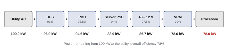
Power from the utility reaches a processor through a chain of conversions, and the overall efficiency is the product of the stage efficiencies. Every percentage point lost becomes heat that the cooling system must also remove.
Worked problem
Where 100 kW goes
Using the stage efficiencies in the figure (UPS 96%, PDU 98.5%, server PSU 94%, bus converter 97.5%, voltage regulator 90%), how much of 100 kW drawn from the utility reaches the processors, and how much is lost in conversion? If electricity costs $0.10 per kWh, what is the annual cost of the losses?
Show solution
- Overall: \(0.96 \times 0.985 \times 0.94 \times 0.975 \times 0.90 = 0.780\).
- Delivered: 78.0 kW; lost: 22.0 kW.
- Annual cost of losses: \(22.0 \times 8{,}760 \times 0.10 = \$19{,}300\), before counting the cooling energy to remove the heat.
Answer: 78 kW reaches the chips and 22 kW is lost, costing about $19,300 a year per 100 kW. Raising each stage by one percentage point would recover about 4 kW. This arithmetic drives efficiency standards for power supplies, such as the 80 PLUS certification levels, and the industry's move to fewer conversion stages and higher distribution voltages.
In the US, the Department of Energy sets minimum efficiency requirements for external power supplies and distribution transformers, and ENERGY STAR specifications cover servers and UPS systems.
Common mistakes
MistakeDesigning power systems for maximum power transfer.
InsteadPower systems need RL ≫ Rth for high efficiency and stable voltage.
MistakeIgnoring battery internal resistance.
InsteadInclude it: it sets voltage sag, internal heating and usable capacity.
MistakeTreating constant-power loads as constant-resistance loads.
InsteadConstant-power loads draw more current as voltage falls.
MistakeUsing a linear regulator for a large voltage drop at high current.
InsteadUse a switching regulator; reserve linear regulators for small drops or low noise.
MistakeAdding stage losses instead of multiplying efficiencies.
InsteadOverall efficiency is the product of stage efficiencies.
Summary and key terms
- Efficiency of delivery is RL/(Rth + RL); maximum power transfer gives only 50%.
- Batteries are modeled as an open-circuit voltage with internal resistance; constant-power loads raise current as voltage sags.
- Conductor loss scales with the square of current, so higher distribution voltage cuts loss dramatically.
- Racks are moving from 12 V to 48 V and higher DC distribution as power rises.
- Linear regulators are at best Vout/Vin efficient; switching regulators reach 85–97%.
- Overall efficiency is the product of the stage efficiencies.
- Efficiency
- The ratio of useful output power to input power.
- Internal resistance
- The resistance inside a source that causes voltage sag and loss.
- Constant-power load
- A load, such as a regulated converter, that draws fixed power regardless of voltage.
- Distribution voltage
- The voltage at which power is carried to loads.
- Busbar
- A rigid conductor that distributes high current.
- Linear regulator
- A regulator that drops excess voltage across a transistor.
- Switching regulator
- A regulator that uses rapid switching and energy storage to convert voltage efficiently.
- Buck converter
- A switching regulator that steps voltage down.
- Voltage regulator module
- The converter that supplies a processor's core voltage.
- Efficiency chain
- A series of conversion stages whose efficiencies multiply.
Practice problems
Work each problem on paper first, then reveal the answer to check.
Rth = 1 Ω, RL = 19 Ω. Efficiency?
Show answer
95%.
What load gives maximum power from Vth = 12 V, Rth = 3 Ω, and what is that power?
Show answer
3 Ω; 12 W.
A 12.6 V battery with 20 mΩ internal resistance supplies 150 A. Terminal voltage?
Show answer
9.6 V.
Internal loss in that battery?
Show answer
450 W.
Four strings in parallel, each 0.2 Ω. Combined internal resistance?
Show answer
0.05 Ω.
Doubling the distribution voltage at the same power changes conductor loss by what factor?
Show answer
It falls to one quarter.
20 kW rack at 48 V. Current?
Show answer
417 A.
Linear regulator 5 V to 1.8 V at 1 A. Heat and efficiency?
Show answer
3.2 W; 36%.
Stages of 98%, 95% and 92%. Overall efficiency?
Show answer
85.7%.
10 kW lost continuously at $0.12/kWh. Annual cost?
Show answer
$10,512.
Lesson quiz · 5 questions
Score 60% or more to complete this lesson.
Create a free account to save your progress, take quizzes and earn a certificate.