
ELE-202 · Lesson 3 of 12 · 38 min
Resistive networks in practice
Lessons 1 and 2 treated resistors as ideal: exact values, unlimited power, no effect from the instruments used to measure them. Real circuits are built from parts with tolerances, temperature coefficients and power limits, and they are measured with instruments that draw current and add resistance of their own. This lesson applies Kirchhoff's laws to the questions an engineer meets when a resistive circuit leaves the page: how far can the output of a divider stray, how hot will a resistor run, how much does a meter disturb the reading, how are tiny resistance changes detected with a bridge, and how are large currents measured with a shunt?
Real resistors
A resistor's marked value is nominal. Three specifications describe how the real value differs:
- Tolerance: the permitted deviation at manufacture, typically ±5% or ±1% for general-purpose parts and ±0.1% or better for precision parts.
- Temperature coefficient of resistance (TCR), in parts per million per degree Celsius (ppm/°C): about ±100 ppm/°C for thick-film chips, ±25 ppm/°C or better for thin-film and metal-film parts, and a few ppm/°C for precision foil resistors.
- Long-term stability: drift with age, load and humidity, often a few tenths of a percent over the life of a general-purpose part.
Standard values follow the IEC 60063 E-series, in which values are spaced evenly on a logarithmic scale. The E12 series (12 values per decade: 10, 12, 15, 18, 22, 27, 33, 39, 47, 56, 68, 82) suits ±10% parts; E24 suits ±5%; E96 suits ±1%. A designer who calculates a needed resistance of 13.7 kΩ picks the nearest standard value, or a combination, and checks that the circuit still meets its specification.
Worked problem
Worst-case output of a divider
A divider of two nominal 10 kΩ resistors across a 12 V reference should give 6 V. Find the extreme outputs with ±5% resistors and with ±1% resistors.
Show solution
- The output \(V_{o} = V_{s} R_{2}/(R_{1} + R_{2})\) is highest when \(R_{2}\) is high and \(R_{1}\) low.
- ±5%: \(V_{max} = 12 \times 10.5/(9.5 + 10.5) = 6.30\) V; \(V_{min} = 12 \times 9.5/(10.5 + 9.5) = 5.70\) V.
- ±1%: \(V_{max} = 12 \times 10.1/(9.9 + 10.1) = 6.06\) V; \(V_{min} = 5.94\) V.
Answer: The output can be anywhere from 5.70 V to 6.30 V with ±5% parts, and 5.94 V to 6.06 V with ±1% parts. Worst-case analysis like this guarantees a design works with every combination of parts; statistical (Monte Carlo) analysis, covered in Lesson 12, estimates how many units would fall outside a tighter limit.
Because a divider's output depends on a ratio, matched resistors help: resistor networks made on one substrate track each other closely in temperature and age, so the ratio stays stable even when absolute values drift.
Power ratings and derating
Every resistor has a rated power, the maximum it can dissipate continuously at a stated ambient temperature, usually 70 °C. Above that, the allowed power is reduced linearly, typically to zero at the maximum element temperature (often 125 °C or 155 °C). Resistors also have a maximum working voltage, which limits high-value parts before their power rating does.
Worked problem
How much can it take?
A 1 kΩ resistor is rated 0.25 W at 70 °C, derating linearly to zero at 155 °C. (a) What is the maximum voltage across it at 70 °C? (b) What power is allowed at an ambient of 100 °C, as inside a hot enclosure?
Show solution
- (a) \(V = \sqrt{PR} = \sqrt{0.25 \times 1000} = 15.8\) V.
- (b) Derating factor: \((155 - 100)/(155 - 70) = 55/85 = 0.647\). Allowed power: \(0.647 \times 0.25 = 0.162\) W.
Answer: 15.8 V at 70 °C, and 0.162 W at 100 °C. Good practice is to operate resistors at no more than about half their derated power, because temperature shortens their life and shifts their value. A resistor running at full rating can reach well over 100 °C at its surface.
Measurement and loading
Every instrument connected to a circuit becomes part of it. An ideal voltmeter has infinite resistance and an ideal ammeter zero; real ones do not, and the difference is called loading.
Voltmeter loading
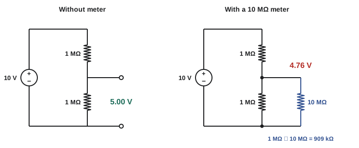
A digital multimeter typically has an input resistance of 10 MΩ on its DC voltage ranges. Connected across a low-resistance part of a circuit, it draws negligible current; connected across a high-resistance node, it forms a parallel combination that pulls the voltage down.
Worked problem
How much does the meter disturb the reading?
Two 1 MΩ resistors divide 10 V. A meter with 10 MΩ input resistance is connected across the lower resistor. What does it read, and what is the error? What if the resistors were 10 kΩ?
Show solution
- Lower resistor in parallel with the meter: \(1 \parallel 10 = 10/11 = 0.909\) MΩ.
- Reading: \(10 \times 0.909/(1 + 0.909) = 4.76\) V instead of 5.00 V, an error of −4.8%.
- With 10 kΩ resistors: \(10 \parallel 10{,}000 = 9.990\) kΩ; reading \(10 \times 9.990/19.990 = 4.9975\) V, an error of −0.05%.
Answer: 4.76 V, a 4.8% error, with 1 MΩ resistors, but only 0.05% with 10 kΩ. The rule of thumb is that the meter's resistance should be at least 100 times the Thévenin resistance of the node being measured (Lesson 6) to keep loading error below about 1%.
Ammeter burden
An ammeter is inserted in series and adds its own resistance, causing a burden voltage. A multimeter's current ranges use internal shunt resistors, often adding a few hundred millivolts at full scale. In a low-voltage circuit this can change the current being measured. Clamp meters, which sense the magnetic field around a conductor, avoid the problem entirely for larger currents.
Worked problem
Burden in a low-voltage circuit
A 3.3 V supply drives a 10 Ω load. A multimeter on its 400 mA range, with a 1 Ω internal shunt plus 0.2 Ω of fuse and lead resistance, is inserted to measure the current. What does it read and what is the error?
Show solution
- True current: \(3.3/10 = 330\) mA.
- With the meter: \(3.3/(10 + 1.2) = 294.6\) mA.
- Error: \((294.6 - 330)/330 = -10.7\%\).
Answer: The meter reads about 295 mA, almost 11% low, because it has changed the circuit. Measuring the voltage across a known small resistor already in the circuit, or using a clamp or Hall-effect sensor, avoids the burden.
Current shunts
Large currents are measured with a shunt: a precise, low-value resistor placed in series, across which the voltage is measured. Shunts are rated by current and full-scale voltage, such as 400 A at 50 mV. They are made of alloys such as manganin, whose resistance hardly changes with temperature, and have separate sense terminals so that the voltage is measured across the resistive element alone, not the high-current connections.
Worked problem
Specifying a shunt
A battery string in a UPS is monitored with a 400 A, 50 mV shunt. (a) What is its resistance? (b) How much power does it dissipate at 400 A? (c) What voltage does a 120 A discharge produce?
Show solution
- (a) \(R = 0.050/400 = 0.125\) mΩ.
- (b) \(P = 0.050 \times 400 = 20\) W.
- (c) \(V = 120 \times 0.000125 = 15\) mV.
Answer: 0.125 mΩ, 20 W at full current, and 15 mV at 120 A. The tiny signal must be amplified accurately, usually by a differential amplifier with high common-mode rejection (Lesson 9), and the shunt must be cooled and mounted so that its own heating does not change its value. Shunts are typically operated at no more than about two-thirds of their rated current continuously.
Four-wire (Kelvin) measurement
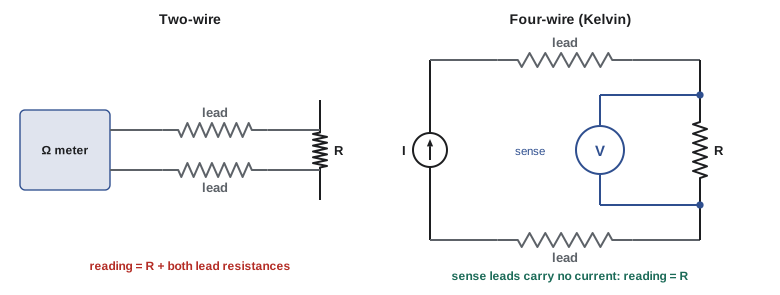
When the resistance being measured is small, or the leads are long, the resistance of the leads themselves adds to the reading. A four-wire (Kelvin) connection solves this: one pair of wires carries a known test current, and a separate pair, carrying almost no current, senses the voltage directly at the resistor. Because negligible current flows in the sense leads, their resistance causes no error.
Worked problem
An RTD with two-wire leads
A Pt100 platinum resistance temperature detector reads 100.0 Ω at 0 °C and changes by about 0.385 Ω/°C. It is connected through two leads of 0.4 Ω each. With a two-wire connection, what temperature does the instrument report when the sensor is at exactly 0 °C?
Show solution
- Measured resistance: \(100.0 + 2 \times 0.4 = 100.8\) Ω.
- Apparent temperature: \(0.8/0.385 = 2.1\) °C.
Answer: About 2.1 °C too high. Three-wire connections, which cancel the lead resistance if both leads match, and four-wire connections, which remove it entirely, are standard for RTDs in building management and data center temperature monitoring.
Bridge circuits
The Wheatstone bridge (Lesson 2) is two dividers fed from the same source, with the output taken between their midpoints. When the ratios match, the output is zero regardless of the supply voltage, which makes the bridge ideal for detecting small changes in one resistance.
Strain gauges, load cells and pressure sensors use this principle. A strain gauge is a fine metal foil pattern bonded to a surface; stretching it lengthens and narrows the conductor, raising its resistance in proportion to the strain \(\varepsilon\): \(\Delta R/R = GF \cdot \varepsilon\), where the gauge factor \(GF\) is about 2 for metal foil.
Worked problem
A quarter-bridge strain gauge
A 120 Ω strain gauge with gauge factor 2.0 forms one arm of a bridge whose other arms are fixed 120 Ω resistors, excited at 5 V. The structure is strained by 500 µε (microstrain, \(500 \times 10^{-6}\)). Find the bridge output.
Show solution
- \(\Delta R/R = 2.0 \times 500 \times 10^{-6} = 0.001\), so \(\Delta R = 0.12\) Ω and \(R_{x} = 120.12\) Ω.
- Exact output: \(5 \times (120.12/240.12 - 0.5) = 5 \times 0.0002499 = 1.249\) mV.
- Small-change approximation: \(V_{o} \approx (V_{s}/4)(\Delta R/R) = 1.25 \times 0.001 = 1.25\) mV.
Answer: About 1.25 mV for a strain that changes the gauge by only 0.12 Ω. Such small signals need careful amplification (Lesson 9). Half-bridge and full-bridge arrangements, with two or four active gauges, double or quadruple the output and cancel the effects of temperature on the gauges.
Ladder networks
A ladder network alternates series and shunt elements. It is solved from the far end back toward the source, combining as you go, or by working forward from an assumed output voltage (the "unit output" method): assume 1 V at the output, compute currents and voltages back to the source, then scale everything so that the source has its real value.
An infinite ladder of identical series resistors \(R\) and shunt resistors \(R\) has an input resistance that is unchanged by adding one more section, so \(R_{in} = R + R \parallel R_{in}\). Solving the resulting quadratic gives \(R_{in} = R(1 + \sqrt{5})/2 \approx 1.618R\), the golden ratio, a neat result and a useful model of long transmission lines with leakage.
The R-2R ladder
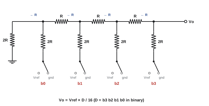
The R-2R ladder uses only two resistor values and is the basis of many digital-to-analog converters (DACs). Looking toward the terminated end from any node, the resistance is exactly R, so at each node the current splits equally. Each bit therefore contributes a current half as large as the bit before, and the output is proportional to the binary number applied.
Worked problem
A 4-bit DAC
A 4-bit R-2R DAC has a reference of 5.000 V and an unloaded output \(V_{o} = V_{ref} \cdot D/16\), where \(D\) is the binary input. Find the output for D = 1011 and the size of one step.
Show solution
- 1011 in binary is \(8 + 2 + 1 = 11\).
- \(V_{o} = 5 \times 11/16 = 3.4375\) V.
- One step (least significant bit): \(5/16 = 0.3125\) V.
Answer: 3.4375 V, in steps of 0.3125 V. Real DACs have 12 to 24 bits, so the resistors must match to better than one part in \(2^{n}\): about 0.025% for 12 bits. That is achieved by laser-trimming thin-film resistors on the chip.
Common mistakes
MistakeDesigning with nominal resistor values only.
InsteadCheck worst-case limits from tolerance and temperature coefficient.
MistakeRunning resistors at their full power rating in a hot enclosure.
InsteadDerate for ambient temperature and keep to about half the derated power.
MistakeIgnoring meter loading on high-resistance nodes.
InsteadCompare the meter resistance with the node's Thévenin resistance; aim for at least 100 times.
MistakeMeasuring low resistances or long-lead sensors with two wires.
InsteadUse four-wire (Kelvin) or three-wire connections.
MistakeMeasuring a shunt voltage at its current terminals.
InsteadUse the separate sense terminals.
Summary and key terms
- Real resistors have tolerance, temperature coefficient, drift, power and voltage limits.
- Worst-case analysis combines extreme values to bound a circuit's output.
- Resistor power ratings must be derated above about 70 °C ambient.
- Voltmeters load high-resistance nodes; ammeters add burden voltage.
- Shunts measure large currents as small voltages; Kelvin connections remove lead resistance.
- Bridges detect small resistance changes, as in strain gauges: \(V_{o} \approx (V_{s}/4)\,\Delta R/R\).
- Ladders are solved from the far end; R-2R ladders form binary-weighted DACs.
- Tolerance
- The permitted deviation of a component from its nominal value.
- TCR
- Temperature coefficient of resistance, in ppm/°C.
- E-series
- Standard sets of preferred component values spaced logarithmically.
- Derating
- Reducing allowed power at high ambient temperature.
- Loading
- The change in a circuit caused by connecting an instrument or load.
- Burden voltage
- The voltage dropped across an ammeter.
- Shunt
- A precise low-value resistor used to measure current.
- Kelvin connection
- Four-wire measurement with separate current and sense leads.
- Gauge factor
- The ratio of fractional resistance change to strain.
- R-2R ladder
- A resistor network using values R and 2R to form binary-weighted currents.
Practice problems
Work each problem on paper first, then reveal the answer to check.
A 4.7 kΩ ±5% resistor: allowed range?
Show answer
4.465 to 4.935 kΩ.
A 100 ppm/°C resistor warms by 40 °C. Change in value?
Show answer
0.4%.
Maximum voltage across a 0.125 W, 10 kΩ resistor?
Show answer
35.4 V.
A 10 MΩ meter measures a node with 500 kΩ Thévenin resistance. Approximate loading error?
Show answer
−500/10,500 ≈ −4.8%.
Shunt rated 100 A at 75 mV. Resistance?
Show answer
0.75 mΩ.
That shunt reads 30 mV. Current?
Show answer
40 A.
Pt100 with 2 × 1 Ω leads, two-wire. Temperature error?
Show answer
About +5.2 °C.
Quarter bridge, 10 V excitation, ΔR/R = 0.002. Output?
Show answer
About 5 mV.
Input resistance of an infinite R–R ladder with R = 1 kΩ?
Show answer
About 1.618 kΩ.
8-bit R-2R DAC, 2.56 V reference. Step size and output for D = 100?
Show answer
10 mV; 1.00 V.
Lesson quiz · 5 questions
Score 60% or more to complete this lesson.
Create a free account to save your progress, take quizzes and earn a certificate.