
MATH-300 · Lesson 11 of 12 · 24 min
An introduction to the finite element method
Finite differences work beautifully on rectangular grids, but engineering parts are not rectangles: a bracket with holes and fillets, a turbine blade, a dam on an irregular valley, a bone, a car body. The finite element method (FEM) handles such shapes by dividing the region into simple pieces (elements), approximating the solution by a simple function on each, and assembling the pieces into one large sparse system. It is the basis of the structural, thermal and electromagnetic analysis software used throughout engineering. This lesson develops the method in one dimension, where every step can be done by hand: the weak form of the governing equation, piecewise linear shape functions, element stiffness matrices and load vectors, assembly, boundary conditions and convergence. It then explains how the same ideas extend to two and three dimensions, and what an engineer must understand to use commercial FEM software responsibly.
The model problem: an axially loaded bar
A bar along \(0 \le x \le L\) with axial stiffness EA(x) carries a distributed axial load f(x) (such as its own weight). Equilibrium of a short slice gives the differential equation for the axial displacement u(x):
with, for example, a fixed end \(u(0) = 0\) and an end load \(EA\,u'(L) = P\). The same equation, with different symbols, governs steady heat conduction along a rod (temperature, conductivity, heat source), seepage through a soil column and electrostatics in one dimension, so everything below applies to those too.
The weak form
Instead of requiring the equation to hold at every point, multiply it by an arbitrary test function v(x) that is zero where u is prescribed, and integrate over the bar. Integrating the left side by parts (MATH-101) moves one derivative onto v:
This weak form must hold for every admissible v. It needs only first derivatives of u, so it admits approximations that are merely continuous, with kinks at element boundaries. The end load appears automatically in the boundary term: conditions on the derivative (forces, heat fluxes) are natural boundary conditions, satisfied by the weak form itself, while conditions on the value (fixed displacements, set temperatures) are essential boundary conditions, imposed directly on the unknowns. For elastic problems, the weak form is exactly the principle of virtual work, so it has a direct physical meaning: internal virtual work equals external virtual work for every virtual displacement.
Elements and shape functions
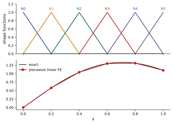
Divide the bar into elements between nodes \(x_0, x_1, \ldots, x_n\), and approximate u by a continuous function that is linear on each element. Such a function is determined by its nodal values \(u_j\):
where the shape function \(N_j\) is the hat function that equals 1 at node j, 0 at all other nodes, and is linear in between. The Galerkin method uses the same hat functions as test functions. Substituting into the weak form with \(v = N_i\), for each free node i, gives a linear system \(K\mathbf{u} = \mathbf{F}\) with
Because each hat function is non-zero only on the two elements touching its node, \(K_{ij}\) is zero unless nodes i and j share an element. The stiffness matrix is therefore sparse (tridiagonal in one dimension), symmetric and, once the essential conditions are applied, positive definite (MATH-125).
Element matrices and assembly
In practice K is not computed entry by entry. Each element of length h contributes only to its own two nodes. On an element with constant EA, the shape function derivatives are \(\mp 1/h\), and the element stiffness matrix and load vector (for a uniform load f) are
This is simply a spring of stiffness EA/h between two nodes, with the element's load shared equally. Assembly adds each element matrix into the rows and columns of the global matrix that correspond to its nodes. Essential conditions are then applied, typically by deleting the rows and columns of fixed degrees of freedom, and the system is solved. Afterwards, element strains and stresses are recovered from the nodal displacements: in each element, \(\varepsilon = (u_{right} - u_{left})/h\).
Worked problem
A bar hanging under its own weight
A uniform bar of length L, fixed at the top (x = 0), hangs under its own weight w per unit length. Solve with two equal elements and compare with the exact solution \(u = \dfrac{w}{EA}\left(Lx - \dfrac{x^2}{2}\right)\).
Show solution
- Elements of length h = L/2, each with \(k = \dfrac{2EA}{L}\begin{pmatrix} 1 & -1 \\ -1 & 1 \end{pmatrix}\) and load \(\tfrac{wL}{4}\) at each of its nodes.
- Assembled for nodes 0, 1, 2: the middle node collects load from both elements, \(F = \tfrac{wL}{4}(1, 2, 1)\).
- Removing the fixed node 0: \(\dfrac{2EA}{L}\begin{pmatrix} 2 & -1 \\ -1 & 1 \end{pmatrix}\begin{pmatrix} u_1 \\ u_2 \end{pmatrix} = \dfrac{wL}{4}\begin{pmatrix} 2 \\ 1 \end{pmatrix}\).
- Solving: \(u_1 = \dfrac{3wL^2}{8EA}\), \(u_2 = \dfrac{wL^2}{2EA}\).
Answer: Both nodal displacements equal the exact values 3wL²/(8EA) and wL²/(2EA). For this one-dimensional problem, linear elements are exact at the nodes; between nodes the approximation is linear while the exact solution is quadratic, so the stress (constant in each element) is only approximate, equal to the exact value at each element midpoint.
Convergence
With linear elements of size h, the error in displacement falls as \(h^2\) and the error in stress (a derivative) as h, provided the exact solution is smooth. Refining the mesh (h-refinement) or using higher-order elements, quadratic or cubic (p-refinement), improves accuracy. The code below models a tapered bar, where EA varies along the length and the nodal values are no longer exact, and shows the expected convergence.
import numpy as np

# Tapered steel bar: area falls linearly from A0 at the support to A0/2 at the free end, end load P
E, A0, L, P = 200e9, 4e-4, 2.0, 50e3
exact_tip = P * 2 * L * np.log(2) / (E * A0)

def fe_bar(n):
    h = L / n
    K = np.zeros((n + 1, n + 1))
    F = np.zeros(n + 1)
    for e in range(n):
        xm = (e + 0.5) * h
        EA = E * A0 * (1 - xm / (2 * L))          # stiffness at the element midpoint
        k = EA / h * np.array([[1.0, -1.0], [-1.0, 1.0]])
        K[e:e + 2, e:e + 2] += k                   # assembly
    F[-1] = P                                      # end load at the last node
    u = np.zeros(n + 1)
    u[1:] = np.linalg.solve(K[1:, 1:], F[1:])      # node 0 is fixed: remove its row and column
    return u[-1]

prev = None
for n in [1, 2, 4, 8, 16]:
    tip = fe_bar(n)
    err = abs(tip - exact_tip)
    ratio = f"{prev / err:5.2f}" if prev else "   --"
    print(f"{n:2d} elements: tip displacement {tip * 1000:.5f} mm, error {err * 1000:.2e} mm, ratio {ratio}")
    prev = err
print(f"Exact: {exact_tip * 1000:.5f} mm")1 elements: tip displacement 1.66667 mm, error 6.62e-02 mm, ratio -- 2 elements: tip displacement 1.71429 mm, error 1.86e-02 mm, ratio 3.56 4 elements: tip displacement 1.72805 mm, error 4.82e-03 mm, ratio 3.86 8 elements: tip displacement 1.73165 mm, error 1.22e-03 mm, ratio 3.96 16 elements: tip displacement 1.73256 mm, error 3.05e-04 mm, ratio 3.99 Exact: 1.73287 mm
The error falls by four with each doubling of the element count, and 16 elements give the tip displacement to within 0.02%. One element is too stiff, as finite element models with too few elements usually are: the displacement-based method always underestimates the true flexibility, so coarse models predict deflections that are too small.
Two and three dimensions
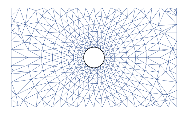
In two dimensions the region is divided into triangles or quadrilaterals, and in three into tetrahedra or bricks. Shape functions are linear (or higher-order) polynomials on each element, equal to 1 at one node and 0 at the others, exactly as in one dimension. The weak form of the governing equation, for instance the equilibrium of an elastic solid or steady heat conduction, gives element matrices by integrating products of shape-function derivatives over each element, usually by Gauss quadrature (Lesson 7) on a reference element mapped to the real one with a Jacobian (MATH-209). Assembly, boundary conditions and the sparse solve are the same, only larger: a model with a million nodes and three displacements per node has three million unknowns, solved with the sparse direct or iterative methods of Lesson 3. Vibration analysis adds a mass matrix and solves \(K\boldsymbol{\phi} = \omega^2M\boldsymbol{\phi}\) by the Lanczos methods of Lesson 4; transient heat flow adds a capacity matrix and steps in time with the schemes of Lesson 10.
Using finite element software responsibly
Commercial and open-source programs (ANSYS, Abaqus, COMSOL, CalculiX, Code_Aster, FEniCS and others) automate meshing, assembly and solution, and produce persuasive color plots. The engineer remains responsible for the result. Good practice includes:
- Check equilibrium: reactions should balance the applied loads.
- Refine the mesh where results vary quickly (near holes, fillets and loads) and confirm that the quantities of interest converge.
- Beware singularities: at a sharp re-entrant corner or a point load, the theoretical stress is infinite, and refining the mesh makes the computed peak grow without limit. Read stresses away from such points, or model the real fillet radius.
- Use appropriate element types: thin plates and shells, beams and nearly incompressible materials such as rubber need special formulations, or results can be grossly too stiff (locking).
- Validate against hand calculations, simple beam or pressure-vessel formulas, or test data.
Common mistakes
MistakeApplying a force boundary condition by fixing a value.
InsteadForces and fluxes are natural conditions entering the load vector; only displacements and temperatures are essential.
MistakeForgetting to remove or constrain fixed degrees of freedom.
InsteadWithout essential conditions, K is singular (the structure can move as a rigid body).
MistakeTrusting a single coarse mesh.
InsteadRefine and check convergence of the quantities you need.
MistakeReporting the peak stress at a sharp corner or point load.
InsteadThose stresses are singular; model the real geometry or read results away from the singularity.
MistakeExpecting a coarse displacement-based model to be conservative for deflection.
InsteadCoarse meshes are too stiff and underestimate deflections.
Summary and key terms
- The weak form multiplies the equation by test functions and integrates by parts, lowering the derivative order.
- Essential conditions (values) are imposed directly; natural conditions (forces, fluxes) appear in the weak form.
- Galerkin FEM uses hat shape functions for both the approximation and the test functions.
- A linear bar element has stiffness (EA/h)[[1, −1], [−1, 1]], like a spring.
- Element matrices are assembled into a sparse, symmetric, positive definite global matrix.
- Displacement errors fall as h² and stress errors as h for linear elements; coarse meshes are too stiff.
- In 2D and 3D, the same steps apply with triangles, tetrahedra and Gauss quadrature; check equilibrium, convergence and singularities.
- Finite element method
- Approximating a PDE solution by simple functions on many small elements assembled into one system.
- Weak form
- An integral form of a differential equation that holds for all admissible test functions.
- Test function
- A weighting function used to form the weak form.
- Essential boundary condition
- A condition on the value of the solution, imposed directly.
- Natural boundary condition
- A condition on the derivative, satisfied through the weak form.
- Shape function
- A function equal to 1 at one node and 0 at others, used to interpolate within elements.
- Galerkin method
- Using the shape functions as test functions.
- Element stiffness matrix
- The matrix relating an element's nodal forces to its nodal displacements.
- Assembly
- Adding element matrices into the global matrix according to node numbering.
- Stress singularity
- A point where the theoretical stress is infinite, such as a sharp re-entrant corner.
Practice problems
Work each problem on paper first, then reveal the answer to check.
Write the element stiffness matrix for a steel bar element (E = 200 GPa) of area 2 cm² and length 0.5 m.
Show answer
(EA/h) = 80 MN/m: 80[[1, −1], [−1, 1]] MN/m.
Two elements with stiffness k each are joined in a line. Write the assembled 3 × 3 matrix.
Show answer
k[[1, −1, 0], [−1, 2, −1], [0, −1, 1]].
Fix node 0 of that assembly and apply P at node 2. Find u₁ and u₂.
Show answer
u₁ = P/k, u₂ = 2P/k.
What is the element load vector for a uniform load f on an element of length h?
Show answer
(fh/2)(1, 1).
Is a heat flux applied at the end of a rod an essential or natural condition?
Show answer
Natural.
Why is K singular before boundary conditions are applied?
Show answer
A rigid-body translation produces no strain, so Ku = 0 has a non-zero solution.
For linear elements, by what factor should the displacement error fall when h is halved?
Show answer
About 4.
And the stress error?
Show answer
About 2.
In the hanging bar, what stress does the first element report, and what is the exact stress at its midpoint?
Show answer
E(u₁ − 0)/h = 3wL/(4A); exact at x = L/4 is w(L − L/4)/A = 3wL/(4A).
Name two checks on a finite element result.
Show answer
Reactions balance loads; mesh refinement converges (also comparison with hand calculations).
Lesson quiz · 5 questions
Score 60% or more to complete this lesson.
Create a free account to save your progress, take quizzes and earn a certificate.