
MEC-210 · Lesson 7 of 12 · 26 min
Systems of particles and angular momentum
The last three lessons treated one particle at a time. Real machines are made of many parts that push and pull on each other, and many important problems involve a stream of material rather than a single body: sand pouring onto a belt, air passing through a fan, water leaving a nozzle. This lesson extends the three kinetic principles to systems of particles, introduces angular momentum, and applies both to steady streams of mass. It is also the bridge to rigid bodies, which are simply systems of particles that keep fixed distances from each other. Almost every result in Lessons 10 and 11 is a special case of something in this lesson.
The center of mass and its motion
For a system of particles with masses \(m_i\) at positions \(\mathbf{r}_i\), the center of mass \(G\) is the mass-weighted average position, \(\mathbf{r}_G = \sum m_i \mathbf{r}_i / m\), where \(m\) is the total mass. Writing the second law for each particle and adding them up, the internal forces cancel in pairs by Newton's third law, leaving
This is a remarkable result. However the parts of a system move relative to each other, its center of mass moves as if all the mass were concentrated there and all the external forces acted there. A tote whose contents shift during braking, a shuttle carrying a loose load, a two-stage telescoping fork: their centers of mass all obey this one equation, and the internal forces between the parts never enter. The equation does not tell you how each part moves, but it often tells you what you need: the total external force required, or where the system as a whole will end up.
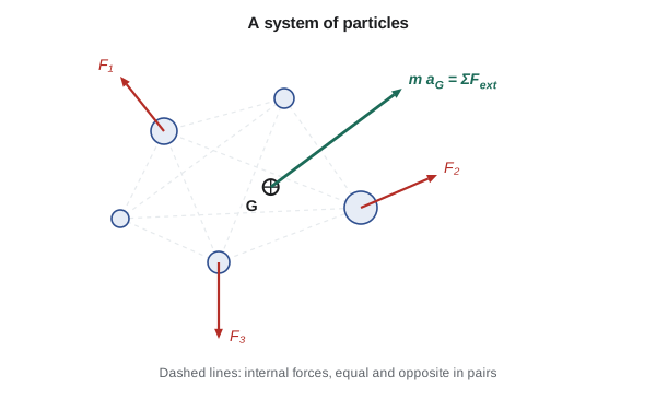
A useful consequence: if the resultant external force on a system is zero in some direction, the center of mass does not accelerate in that direction. If it starts at rest, it stays put. When a person walks forward on a small boat, the boat moves backward so that the center of mass of person and boat stays where it was. When a shuttle's telescoping forks extend sideways on a frictionless rail, the shuttle body shifts the other way. On a real rail, friction is an external force and limits the effect, but on air bearings or well-lubricated slides it can surprise a designer.
Worked problem
Where does the shuttle go?
A shuttle with a mass of 12.3 slugs (weight 396 lb) carries a tote of 1.37 slugs (44 lb) and stands on a level rail with its brakes released. Its forks push the tote 3.0 ft sideways onto a rack, along the direction of the rail. Neglecting rolling resistance, how far does the shuttle move?
Show solution
- No external horizontal force acts on the shuttle-tote system, and it starts at rest, so its center of mass does not move.
- Let the shuttle move \(d\) along the rail and the tote move \(3.0 + d\) relative to the ground (the forks push it 3.0 ft relative to the shuttle).
- \[12.3\,d + 1.37(3.0 + d) = 0 \;\Rightarrow\; d = -\frac{4.11}{13.67} = -0.30 \text{ ft}\]
Answer: The shuttle rolls about 3.6 in. backward. In practice the brakes are applied during fork moves so that the rail supplies the external force needed to hold the shuttle, which is the brake design load this calculation helps estimate.
Work, energy and momentum for systems
The impulse-momentum principle carries over directly: the total linear momentum of a system changes only by the impulse of the external forces, because internal impulses cancel. Work and energy is more subtle. Internal forces act in equal and opposite pairs, but the points where they act can move different distances, so their work does not necessarily cancel. Two blocks joined by a stretched spring, a tote sliding on a shuttle deck, and parts rubbing in a clutch all have internal forces that do net work, either storing energy in a spring or dissipating it as heat. For a system, the work-energy principle must therefore include the work of internal forces as well as external ones:
For rigid bodies the internal forces between particles do no net work, because the particles keep fixed distances. That is one reason rigid-body energy methods (Lesson 11) are so clean. For systems with springs, friction between parts or deformation, the internal work is real and must be accounted for, as the collision examples of Lesson 6 showed.
Angular momentum of a particle
The angular momentum of a particle about a fixed point \(O\) is the moment of its linear momentum about that point:
In plane motion it is a vector perpendicular to the plane, with magnitude \(m v d\), where \(d\) is the perpendicular distance from \(O\) to the line of the velocity. Taking the time derivative and using the second law shows that the resultant moment of the forces about \(O\) equals the rate of change of angular momentum about \(O\):
Integrating over time gives the principle of angular impulse and momentum, \((\mathbf{H}_O)_1 + \sum\int \mathbf{M}_O\,dt = (\mathbf{H}_O)_2\). And if the resultant moment about \(O\) is zero, angular momentum about \(O\) is conserved. This happens whenever every force on the particle passes through \(O\), such as a cord pulling toward a hub or gravity pulling a satellite toward the center of the Earth. Such forces are called central forces.
In polar coordinates with \(O\) at the origin, the angular momentum has magnitude \(m r^2\dot\theta\). Conservation therefore means that \(r^2\dot\theta\) stays constant: as the particle moves closer to \(O\), its angular velocity increases with the inverse square of the distance. Kepler noticed this in planetary orbits four centuries ago; figure skaters exploit it whenever they pull their arms in to spin faster.
Worked problem
Pulling a slider toward the hub
A 0.50 kg slider rides on a light rod that spins freely about a vertical axis at 2.0 rad/s, with the slider 0.60 m from the axis. A cord through the hollow hub pulls the slider in to 0.30 m. Find the new angular velocity and the work done by the cord. Neglect friction and the mass of the rod.
Show solution
- The only horizontal force on the slider is the cord tension, which passes through the axis, so angular momentum about the axis is conserved.
- \[m r_1^2 \dot\theta_1 = m r_2^2 \dot\theta_2 \;\Rightarrow\; \dot\theta_2 = 2.0\Big(\frac{0.60}{0.30}\Big)^2 = 8.0 \text{ rad/s}\]
- Transverse speeds: \(r\dot\theta = 1.20 \text{ m/s}\) before and \(2.40 \text{ m/s}\) after.
- Kinetic energy rises from \(\tfrac12(0.50)(1.20)^2 = 0.36 \text{ J}\) to \(\tfrac12(0.50)(2.40)^2 = 1.44 \text{ J}\). The cord does 1.08 J of work, pulling inward against the slider's tendency to move outward.
Answer: Halving the radius quadruples the spin rate. Angular momentum is conserved, but kinetic energy is not: the cord supplies it.
The example shows that angular momentum and energy are separate accounts. The program below checks the result by integrating the polar equations of motion while the cord pulls the slider in at a steady 0.20 m/s. It confirms that \(m r^2 \dot\theta\) stays constant to four figures and that the work done by the cord tension matches the gain in kinetic energy. The small extra kinetic energy from the radial motion itself, \(\tfrac12 m\dot r^2\), is the same at start and end, so it cancels.
# A 0.50 kg slider on a light, freely spinning rod is pulled toward the hub
# by a cord at a steady 0.20 m/s. No torque acts about the hub, so
# angular momentum H = m r^2 theta_dot should stay constant. Integrate the
# polar equation for theta and check H, then compare the cord's work with
# the change in kinetic energy.
m, r, w = 0.50, 0.60, 2.0          # kg, m, rad/s
rdot = -0.20                        # m/s (cord pulls the slider in)
dt, t = 1e-5, 0.0
work_cord = 0.0
T0 = 0.5 * m * ((r * w)**2 + rdot**2)
H0 = m * r * r * w

while r > 0.30:
    # transverse equation with F_theta = 0:  r*wdot + 2*rdot*w = 0
    wdot = -2 * rdot * w / r
    # radial equation gives the cord tension: -T = m (rddot - r w^2), rddot = 0
    T = m * r * w * w
    work_cord += T * (-rdot) * dt   # tension points inward, slider moves inward
    w += wdot * dt
    r += rdot * dt
    t += dt

T1 = 0.5 * m * ((r * w)**2 + rdot**2)
print(f"after {t:.2f} s: r = {r:.3f} m, omega = {w:.3f} rad/s")
print(f"angular momentum: start {H0:.4f}, end {m * r * r * w:.4f} kg m^2/s")
print(f"kinetic energy: start {T0:.3f} J, end {T1:.3f} J, change {T1 - T0:.3f} J")
print(f"work done by the cord: {work_cord:.3f} J")after 1.50 s: r = 0.300 m, omega = 8.000 rad/s angular momentum: start 0.3600, end 0.3600 kg m^2/s kinetic energy: start 0.370 J, end 1.450 J, change 1.080 J work done by the cord: 1.080 J
The same effect appears in machines. A robot that retracts its arm while slewing freely will speed up unless its drive applies a braking torque; a centrifugal clutch whose shoes fly outward slows the spin of the parts that carry them. Lesson 11 extends conservation of angular momentum to rigid bodies, where the mass moment of inertia takes the place of \(m r^2\).
Steady streams of mass
Many machines move a continuous stream of material: belts carrying bulk solids, pumps and nozzles moving liquid, fans moving air. Applying impulse and momentum to a fixed region of space, a control volume, through which mass flows at a steady rate \(\dot m\), gives
The resultant force on the material in the control volume equals the mass flow rate times the change in velocity between where it enters and where it leaves. This is how the thrust of a jet, the force on a pipe bend and the reaction on a fire hose nozzle are found. It also gives the force a conveyor needs to accept material.
Worked problem
Loading a belt conveyor
Sand drops vertically onto a horizontal belt at 90 lb/s and is carried away at the belt speed of 6.5 ft/s. What extra horizontal force must the belt drive supply to accelerate the sand, and what extra power does that take?
Show solution
- Choose a control volume around the loading zone. Sand enters with zero horizontal velocity and leaves at 6.5 ft/s. The mass flow is \(90/32.2 = 2.80\) slug/s.
- \[F = \dot m (v_{out} - v_{in}) = 2.80(6.5 - 0) = 18.2 \text{ lb}\]
- The belt moves at 6.5 ft/s, so the power is \(P = Fv = 18.2(6.5) = 118 \text{ ft·lb/s}\), about 0.21 hp.
- The kinetic energy given to the sand per second is \(\tfrac12 \dot m v^2 = 59 \text{ ft·lb/s}\), only half the power supplied.
Answer: The drive needs an extra 18 lb and about 0.21 hp at the loading point. Half of that power goes into the sand's kinetic energy and the other half is lost as heat while the sand slides and settles on the belt.
The factor of one half is not a quirk of this example. Whenever material is accelerated to a belt's speed by sliding friction, exactly half of the work done ends up as heat, whatever the friction coefficient. It is the continuous version of the perfectly plastic impact in Lesson 6. Conveyor designers reduce the loss, and the wear and dust that come with it, by feeding material in the direction of belt travel at close to belt speed, using curved chutes or accelerator belts. That is the same idea as matching speeds at a parcel transfer.
Common mistakes
MistakeIncluding internal forces in ΣF = m a_G.
InsteadInternal forces cancel; only external forces move the center of mass.
MistakeAssuming internal forces do no net work in every system.
InsteadThey do no net work only in rigid bodies; springs and friction between parts do work.
MistakeAssuming kinetic energy is conserved when angular momentum is.
InsteadThey are independent; a cord or drive can do work while angular momentum stays constant.
MistakeUsing r instead of the perpendicular distance when computing angular momentum.
InsteadUse H = m v d, with d perpendicular to the velocity.
MistakeForgetting that half the power is lost when a belt accelerates material by friction.
InsteadPower is ṁv², of which only ½ṁv² becomes kinetic energy.
Summary and key terms
- The center of mass moves as if all mass and all external forces were concentrated there.
- With no external force in a direction, the center of mass does not accelerate in that direction.
- For systems, internal forces may do net work; for rigid bodies they do not.
- Angular momentum about O is H_O = r × mv; ΣM_O = dH_O/dt.
- Central forces conserve angular momentum, so r²θ̇ stays constant.
- For steady mass flow, ΣF = ṁ(v_out - v_in).
- Accelerating material onto a belt by friction wastes half the power as heat.
- Center of mass
- The mass-weighted average position of a system.
- Internal force
- A force between parts of the same system.
- External force
- A force on the system from outside it.
- Angular momentum
- The moment of linear momentum about a point.
- Central force
- A force that always passes through a fixed point.
- Angular impulse
- The time integral of a moment.
- Control volume
- A fixed region of space through which mass flows.
- Mass flow rate
- The mass passing a section per unit time.
Practice problems
Work each problem on paper first, then reveal the answer to check.
A 70 kg person walks 3 m along a 140 kg raft at rest on still water. How far does the raft move?
Show answer
1 m in the opposite direction.
A satellite's distance from Earth's center halves between two points of its orbit. How does its transverse speed change?
Show answer
It doubles, because r v_θ stays constant.
In the slider example, what is the angular velocity if the slider is pulled in to 0.20 m?
Show answer
2.0 x (0.6/0.2)² = 18 rad/s.
Water leaves a nozzle at 15 m/s with a flow of 2 kg/s. What thrust does the nozzle feel?
Show answer
F = 2 x 15 = 30 N, opposite to the jet.
If the sand in the belt example were fed in the direction of travel at 1.5 m/s, what force would the belt need?
Show answer
F = 40 x (2.0 - 1.5) = 20 N, a quarter of the original.
Change the program so the cord pulls at 0.10 m/s. Does the final angular velocity change?
Show answer
No; it depends only on the radii, though the process takes twice as long.
Lesson quiz · 5 questions
Score 60% or more to complete this lesson.
Create a free account to save your progress, take quizzes and earn a certificate.