
ROB-220 · Lesson 12 of 12 · 30 min
Capstone: specifying sensors and actuators for a robot
The previous eleven lessons covered the parts. This capstone puts them together in the way an engineer actually works: starting from what a robot must do, deriving requirements, sizing actuators from loads and duty cycles, choosing sensors to cover the tasks and each other's weaknesses, and checking the result against power, data and budget limits. The example is an autonomous mobile robot (AMR) that carries totes around a warehouse and lifts them onto shelves. The same method applies to an arm joint, a drone or a legged robot, and the worked examples show each step.
Step 1: from tasks to requirements
Good specifications begin with the tasks and the environment, not with parts. The warehouse AMR must carry a payload of up to 60 kg on a 40 kg chassis; drive at up to 1.5 m/s on level concrete with occasional 3 % ramps; accelerate at 0.5 m/s²; stop safely for people; localize to within 2 cm at shelf stations; lift a 20 kg tote 0.6 m in 3 s; run an 8-hour shift on one charge; and work among people, other robots, glass partitions and shiny wrapped pallets. Each statement becomes one or more numbers, and each number has a reason. Writing the reason down matters, because requirements without reasons are impossible to trade off later.
| Requirement | Value | Drives the choice of |
|---|---|---|
| Total mass | 100 kg (40 kg robot + 60 kg payload) | Drive motors, gearboxes, battery |
| Top speed and acceleration | 1.5 m/s, 0.5 m/s² | Motor speed, gear ratio, peak torque |
| Ramp | 3 % grade | Continuous torque |
| Stopping | Safe stop for detected people | Safety-rated lidar, brakes |
| Positioning at stations | ±2 cm | Localization sensors and fusion |
| Lift | 20 kg through 0.6 m in 3 s | Lift actuator and screw |
| Endurance | 8 h shift | Battery capacity and efficiency |
| Environment | People, glass, shiny wrap, dust | Complementary sensor set |
Step 2: drive torque and speed
For a wheeled robot, the wheel torque must overcome rolling resistance, climb grades and accelerate the robot. With two driven wheels of radius r sharing the load, the torque per wheel is:
Worked problem
Wheel torque and speed
The AMR has a total mass of 100 kg, two drive wheels of radius 0.075 m and a rolling-resistance coefficient of 0.015 on concrete. Find the wheel torque for (a) cruising on the level, (b) climbing the 3 % ramp at constant speed and (c) accelerating at 0.5 m/s² on the level. Then find the wheel speed at 1.5 m/s.
Show solution
- (a) Level cruise: \( F = 100 \times 9.81 \times 0.015 = 14.7 \) N; per wheel \( \tau = 0.075 \times 14.7/2 = 0.55 \) N·m.
- (b) Ramp: \( \sin\theta \approx 0.03 \); \( F = 981 \times (0.015 + 0.03) = 44.1 \) N; \( \tau = 0.075 \times 44.1/2 = 1.65 \) N·m.
- (c) Accelerating: \( F = 14.7 + 100 \times 0.5 = 64.7 \) N; \( \tau = 0.075 \times 64.7/2 = 2.43 \) N·m.
- Wheel speed: \( \omega = v/r = 1.5/0.075 = 20 \) rad/s \( \approx 191 \) rpm.
Answer: About 0.55 N·m cruising, 1.65 N·m on the ramp and 2.43 N·m peak when accelerating, per wheel, at up to 191 rpm. A safety margin of around 1.5 to 2 is then applied for wheel inertia, drivetrain losses, floor variation and future payload growth.
Step 3: duty cycle and RMS torque
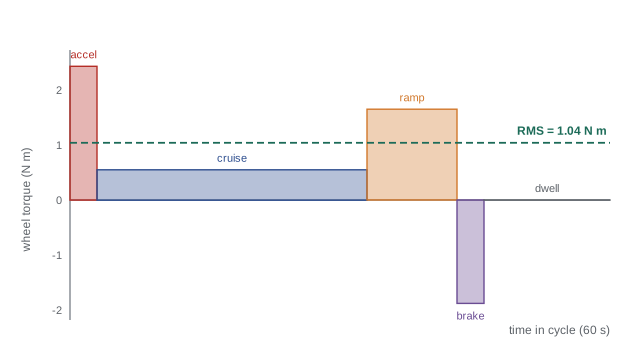
Motors are sized thermally by RMS torque (lesson 8), because heat depends on the square of current. A duty cycle lists the torque in each phase of a typical mission and how long each lasts.
Worked problem
RMS torque over a mission
One 60 s mission cycle for a wheel consists of: accelerate 3 s at 2.43 N·m, cruise 30 s at 0.55 N·m, climb a ramp 10 s at 1.65 N·m, decelerate 3 s at −1.88 N·m and dwell 14 s at 0. Find the RMS wheel torque and the peak.
Show solution
- Squares × times: \( 2.43^2 \times 3 = 17.7 \); \( 0.55^2 \times 30 = 9.1 \); \( 1.65^2 \times 10 = 27.2 \); \( 1.88^2 \times 3 = 10.6 \); dwell 0.
- Sum: \( 64.6 \) N²·m²·s. Divide by 60 s: 1.08.
- RMS: \( \sqrt{1.08} = 1.04 \) N·m. Peak: 2.43 N·m.
Answer: An RMS wheel torque of about 1.04 N·m and a peak of 2.43 N·m. The drive must deliver the RMS torque continuously and the peak briefly; the ratio of about 2.3 between them fits comfortably within a typical motor's peak-to-continuous ratio of 3 or more.
Step 4: choosing motor and gearbox
With torque and speed at the wheel known, choose a ratio and a motor together (lesson 9). A brushless motor with a continuous torque of 0.25 N·m, a peak of 0.75 N·m and a rated speed of 3,000 rpm is a common size. With a planetary gearbox of efficiency 0.90, the ratio must satisfy both speed and torque:
Worked problem
Matching the motor to the wheel
Using the motor above, find a gear ratio that meets the wheel speed of 191 rpm, then check continuous and peak torque against the RMS (1.04 N·m) and peak (2.43 N·m) wheel torques with a safety factor of 1.5.
Show solution
- Speed limit: \( N \leq 3000/191 = 15.7 \). Choose a standard 15:1 planetary.
- Continuous: \( 0.90 \times 15 \times 0.25 = 3.4 \) N·m available versus \( 1.5 \times 1.04 = 1.56 \) N·m needed.
- Peak: \( 0.90 \times 15 \times 0.75 = 10.1 \) N·m available versus \( 1.5 \times 2.43 = 3.65 \) N·m needed.
Answer: A 15:1 planetary gives 191 rpm at 2,865 motor rpm and large torque margins. That suggests a smaller, cheaper motor would do, and a second iteration would check one; the margin, though, helps with heavier loads, worn floors and the motor's own heating in an enclosed chassis.
The lift axis is sized the same way. Lifting 20 kg by 0.6 m in 3 s needs a speed of 0.2 m/s and, at constant speed, a mechanical power of \( mgv = 20 \times 9.81 \times 0.2 = 39 \) W. A ball screw with a 10 mm lead must then turn at 1,200 rpm, and the motor torque required at the screw is \( \tau = F\,l/(2\pi\eta) = 196 \times 0.010/(2\pi \times 0.9) = 0.35 \) N·m before acceleration and friction. A spring-applied brake holds the tote when power is lost, because a ball screw is not self-locking.
Step 5: choosing sensors
Sensors are chosen task by task, then checked for gaps. The AMR needs proprioception for control, perception for safety and navigation, and localization at shelf stations.
- Wheel motors: encoders on each motor (motor-side, multiplied by the 15:1 ratio) for speed control and odometry, plus Hall sensors for commutation.
- Lift: an absolute encoder or linear position sensor, and a limit switch as an independent end-of-travel check.
- Body motion: an industrial-grade IMU fused with wheel odometry to bridge slippage and give heading.
- Safety: a safety-rated 2-D lidar at each end, set with protective and warning fields that trigger stops and slow-downs (safety rating and functional safety are covered in ROB-450).
- Navigation and obstacles: a 3-D depth camera facing forward for overhanging shelf edges and objects above the lidar plane, plus a few ultrasonic or optical time-of-flight sensors to catch glass partitions and close-range blind spots.
- Station localization: a downward or forward camera reading fiducial markers at each station, or UWB, to reach ±2 cm where lidar map matching alone is not precise enough.
- Health: motor currents and temperatures, battery voltage, current and temperature.
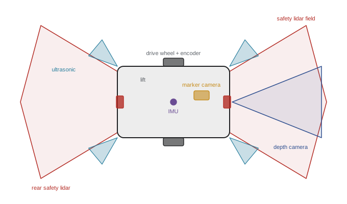
The gap check asks, for every failure mode in the environment, which sensor still works. Glass: ultrasonic. Shiny stretch wrap that scatters lidar: camera and ultrasonic. A person stepping out from behind a shelf: the safety lidar. Slippery floor: IMU and visual or marker localization correct the wheel odometry. An overhanging fork tine: the depth camera. Where the answer is 'nothing', the sensor set is incomplete.
Step 6: power, data and budget checks
Finally, check the totals. Sensors and computers draw power continuously, motors draw it in bursts, and the battery must cover the whole shift. Data rates must fit the robot's networks and computer. And the bill of materials must fit the budget, which often forces a second iteration.
Worked problem
Battery sizing for an 8-hour shift
Average electrical loads over a shift are: drive motors 120 W (averaged over the duty cycle, including losses), lift 15 W, computer 60 W, sensors 35 W and other electronics 20 W. Size a 48 V battery for 8 hours, keeping at least 20 % charge in reserve.
Show solution
- Total average power: \( 120 + 15 + 60 + 35 + 20 = 250 \) W.
- Energy for 8 h: \( 250 \times 8 = 2000 \) Wh. With 20 % reserve, usable fraction 0.8: \( 2000/0.8 = 2500 \) Wh.
- Capacity at 48 V: \( 2500/48 = 52 \) Ah.
Answer: About 2.5 kWh, or roughly 52 Ah at 48 V. The computer and sensors together use about 80 % as much energy as the drive; choosing efficient perception hardware extends runtime as much as better motors do.
import math
# Data budget for the AMR's perception sensors
sensors = {
    "2 x safety lidar (2-D)":   2 * 1100 * 25 * 8,          # points/scan * Hz * bytes
    "depth camera 640x480":     640 * 480 * 30 * 2,         # 16-bit depth at 30 Hz
    "RGB camera 1280x720":      1280 * 720 * 30 * 3 // 20,  # roughly 20:1 compressed
    "marker camera 640x480":    640 * 480 * 15,             # 8-bit mono at 15 Hz
    "IMU + encoders + ultrasonic": 200 * 64 + 4 * 1000 * 8 + 8 * 20 * 8,
}
total = 0
for k, bps in sensors.items():
    total += bps
    print(f"{k:28s} {bps/1e6:7.2f} MB/s")
print(f"{'total':28s} {total/1e6:7.2f} MB/s = {8*total/1e6:6.1f} Mbit/s")2 x safety lidar (2-D) 0.44 MB/s depth camera 640x480 18.43 MB/s RGB camera 1280x720 4.15 MB/s marker camera 640x480 4.61 MB/s IMU + encoders + ultrasonic 0.05 MB/s total 27.67 MB/s = 221.4 Mbit/s
The depth camera dominates the data budget, as it usually does. Around 28 MB/s, about 220 Mbit/s, is comfortable for a USB 3 or gigabit Ethernet link and a modern embedded computer, but logging it all for an 8-hour shift would need roughly 800 GB, so the robot will record selectively. Checks like these, done early, prevent the unpleasant discovery late in a project that the chosen sensors cannot all be connected, powered or processed together.
In the United States, an AMR like this one would also be designed to the safety standards that apply to industrial mobile robots, such as ANSI/A3 R15.08 and ANSI/A3 R15.06, and operated under OSHA's general duty to provide a safe workplace. Its radio modules would carry FCC authorization and its lidars a valid laser classification under FDA rules. ROB-450 covers these requirements.
Common mistakes
MistakeStarting from a favorite sensor or motor instead of the tasks.
InsteadWrite task-based requirements with reasons first, then choose parts that meet them.
MistakeSizing motors by peak torque alone.
InsteadCheck RMS torque over a realistic duty cycle against the continuous rating, and peak torque against the peak rating.
MistakeChoosing a gear ratio for torque without checking top speed.
InsteadRatio must satisfy both torque and speed; iterate between motor and gearbox catalogs.
MistakeSelecting sensors without a failure-mode gap check.
InsteadFor every environmental hazard, name the sensor that still works; add sensors where the answer is none.
MistakeForgetting computers and sensors in the energy budget.
InsteadPerception hardware can use as much energy as the drive; include it when sizing the battery.
Summary and key terms
- Specifications start from tasks and environment, with every number given a reason.
- Wheel torque comes from rolling resistance, grade and acceleration; wheel speed from \( v/r \).
- Thermal sizing uses RMS torque over a duty cycle; peak torque must fit the motor's short-term rating.
- Gear ratio is chosen to satisfy speed and torque together, with margins for uncertainty.
- Sensors are chosen per task, then checked for gaps against every environmental failure mode.
- Power and data budgets often reveal that perception hardware is a major load.
- Design is iterative: requirements, sizing, selection and checks repeat until everything fits.
- Requirement
- A measurable statement of what a system must do, with its reason.
- Rolling resistance
- The force opposing a wheel's rolling, proportional to the normal load.
- Duty cycle
- The sequence and duration of loads in a typical operating cycle.
- RMS torque
- The root-mean-square torque over a duty cycle, which sets motor heating.
- Safety factor
- A margin by which capability exceeds the calculated requirement.
- Lead
- The linear travel of a screw per revolution.
- Spring-applied brake
- A brake held off by power and engaged by springs when power is lost.
- Gap check
- A review of which sensor still works for each failure mode.
- Energy budget
- The total energy a robot needs for its mission, used to size the battery.
- Data budget
- The total data rate the robot's sensors produce.
Practice problems
Work each problem on paper first, then reveal the answer to check.
A 50 kg robot with \( C_{rr} = 0.02 \) cruises on the level. What rolling-resistance force must it overcome?
Show answer
\( 50 \times 9.81 \times 0.02 \approx 9.8 \) N.
What extra force does a 5 % grade add for a 50 kg robot?
Show answer
\( 50 \times 9.81 \times 0.05 \approx 24.5 \) N.
A 0.1 m-radius wheel turns at 15 rad/s. What is the robot speed?
Show answer
1.5 m/s.
Torques of 3 N·m for 2 s and 1 N·m for 8 s make up a cycle. What is the RMS torque?
Show answer
\( \sqrt{(18 + 8)/10} \approx 1.61 \) N·m.
A motor rated 4,000 rpm must drive a wheel at 250 rpm. What is the maximum gear ratio?
Show answer
16.
What power is needed to lift 30 kg at 0.1 m/s?
Show answer
About 29 W.
A ball screw with 5 mm lead must move at 0.05 m/s. What screw speed is needed?
Show answer
10 rev/s, or 600 rpm.
Why does the lift need a brake if it uses a ball screw?
Show answer
Ball screws are efficient and not self-locking, so the load would back-drive the screw when power is lost.
Average loads total 180 W for a 10 h shift with 25 % reserve. What battery energy is needed?
Show answer
\( 1800/0.75 = 2400 \) Wh.
Name a sensor that covers glass partitions which lidar may miss.
Show answer
An ultrasonic sensor.
Lesson quiz · 5 questions
Score 60% or more to complete this lesson.
Create a free account to save your progress, take quizzes and earn a certificate.