
ROB-220 · Lesson 6 of 12 · 31 min
Force, torque and tactile sensing
Position sensors tell a robot where it is; force sensors tell it what it is touching and how hard. They make the difference between a robot that can only follow a programmed path and one that can insert a peg into a tight hole, polish a curved surface, hand an object to a person or stop when it bumps into someone. This lesson explains the strain gauge and the bridge circuit at the heart of most force sensors, builds up to six-axis force-torque sensors and joint torque sensing, and surveys tactile skins. Force control itself, which uses these measurements to command motion, belongs to ROB-300.
Strain gauges
Almost every industrial force sensor measures strain: the tiny fractional change in length of a carefully shaped metal element as it deflects under load. A metal-foil strain gauge is a zigzag pattern of thin foil on a flexible backing, glued to the element. When the element stretches, the foil gets longer and thinner and its resistance rises; when it compresses, the resistance falls. The gauge factor GF relates the fractional resistance change to the strain \( \varepsilon \), and for metal foil gauges it is about 2.
The second equation, Hooke's law, links strain to stress \( \sigma \) through the material's Young's modulus E. The difficulty is scale: a well-designed sensing element is strained to perhaps 500 to 1,000 microstrain (µε, millionths) at full load, so a 350 Ω gauge with GF = 2 changes by only 0.35 to 0.7 Ω, about 0.1 to 0.2 %. Temperature changes the gauge's resistance by a similar amount, so strain gauges are always used in bridge circuits that cancel common effects. Semiconductor gauges have gauge factors of 100 or more but are more temperature-sensitive and nonlinear.
Worked problem
Resistance change of a strain gauge
An aluminum beam (E = 70 GPa) in a load cell reaches a surface stress of 49 MPa at full load. A 350 Ω gauge with GF = 2.1 is bonded to it. What are the strain and the resistance change?
Show solution
- Strain: \( \varepsilon = 49 \times 10^6/70 \times 10^9 = 7.0 \times 10^{-4} = 700 \) µε.
- Fractional change: \( 2.1 \times 7.0 \times 10^{-4} = 1.47 \times 10^{-3} \).
- Resistance change: \( 350 \times 1.47 \times 10^{-3} = 0.51 \) Ω.
Answer: A strain of 700 µε and a resistance change of only about half an ohm out of 350, which is why a bridge and a high-gain amplifier are needed.
The Wheatstone bridge
A Wheatstone bridge arranges four resistances in a diamond, excited by a voltage \( V_{ex} \) across one diagonal, with the output measured across the other. When all four are equal, the output is zero. If one arm changes slightly, the output becomes a small voltage proportional to the change. Using two or four active gauges, placed where the element is in tension and compression, increases the output and makes the bridge self-compensating for temperature, because a uniform temperature rise changes all arms equally and cancels.
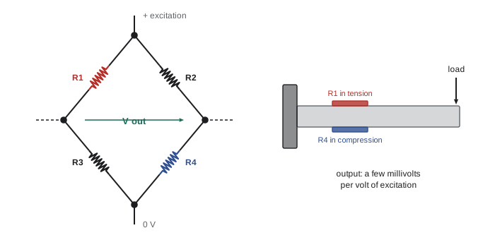
Load cell datasheets quote sensitivity in millivolts per volt (mV/V) at full scale: a 2 mV/V load cell excited at 10 V gives 20 mV at full load. That signal is amplified by an instrumentation amplifier or fed to a dedicated bridge converter with a 24-bit delta-sigma ADC, as ROB-200 described for analog front ends.
Worked problem
Bridge output and resolution
A full bridge of four gauges (GF = 2.0) on a load cell sees ±700 µε at a full load of 500 N. The bridge is excited at 5 V. What is the full-scale output, and what force resolution would a converter with 0.5 µV of effective noise give?
Show solution
- Full bridge: \( V_{out} = V_{ex}\,GF\,\varepsilon = 5 \times 2.0 \times 7 \times 10^{-4} = 7.0 \) mV, that is 1.4 mV/V.
- Sensitivity: \( 7.0 \text{ mV}/500 \text{ N} = 14 \) µV/N.
- Resolution: \( 0.5/14 = 0.036 \) N.
Answer: About 7 mV at full load (1.4 mV/V), giving a force resolution of roughly 0.04 N, or 1 part in about 14,000 of full scale, provided the amplifier and wiring add little noise.
Six-axis force-torque sensors
A load cell measures force along one axis. A robot wrist needs all six components of the wrench: three forces \( (F_x, F_y, F_z) \) and three torques \( (T_x, T_y, T_z) \). Six-axis force-torque (F/T) sensors use a monolithic metal element, often shaped like a wheel with spokes or a cross with beams, carrying many strain gauges. Each load direction strains the beams in a different pattern. A calibration matrix C, found by the manufacturer by applying known loads, maps the vector of gauge signals s to the wrench:
Typical F/T sensors for collaborative arms measure up to a few hundred newtons and tens of newton-meters with resolutions around 0.1 N. Using them well involves three corrections. Bias: subtract the reading with no contact before each task, because the zero drifts with temperature. Gravity compensation: the tool's weight produces a force and a torque that change with orientation, and must be subtracted using the tool's mass and center of mass and the current wrist orientation from forward kinematics. Frame transformation: the measured wrench is expressed in the sensor frame and usually needs moving to the tool tip, which changes the torques as \( \mathbf{T}_{tip} = \mathbf{T}_s - \mathbf{r} \times \mathbf{F} \), where r points from the sensor origin to the tip.
Worked problem
Removing the tool's weight
A 1.2 kg gripper hangs below a wrist F/T sensor, with its center of mass 0.08 m along the sensor's z-axis. With the tool pointing straight down (sensor z-axis aligned with gravity), what force and torque does its weight produce? If the wrist is tilted so the z-axis is horizontal, what torque does the weight produce?
Show solution
- Weight: \( 1.2 \times 9.81 = 11.8 \) N.
- Pointing down: the force is 11.8 N along z, and the torque is zero because the weight acts along the line through the sensor origin.
- Horizontal: the 11.8 N acts at a lever arm of 0.08 m, giving \( 11.8 \times 0.08 = 0.94 \) N·m about a horizontal sensor axis.
Answer: The weight appears as 11.8 N along z when pointing down and as a 0.94 N·m torque when horizontal. Without gravity compensation, a force controller would mistake this changing load for contact.
Joint torque sensing and current-based estimation
An alternative to a wrist F/T sensor is to measure torque in every joint. Collaborative arms from several manufacturers place a strain-gauge torque sensor between the gearbox and the link in each joint, which lets the controller feel contact anywhere along the arm, not just at the wrist, and supports smooth hand-guiding. Others estimate torque without a dedicated sensor, from motor current through the torque constant (lesson 8): \( \tau \approx k_t\,i\,N\,\eta \) for a gear ratio N and efficiency \( \eta \). Current-based estimation is cheap but blurred by gearbox friction, which can be a large and variable fraction of the torque, especially in high-ratio gearboxes. A third option is the dual-encoder joint from lesson 2: a deliberately compliant element whose deflection, measured by encoders on both sides, gives torque through its known stiffness. Lesson 10 develops that idea as the series elastic actuator.
| Approach | Where it senses | Strengths | Weaknesses |
|---|---|---|---|
| Wrist F/T sensor | At the tool | Precise six-axis wrench at the contact | Blind to contact elsewhere; adds mass and cost |
| Joint torque sensors | In every joint | Detects contact anywhere; good hand-guiding | Cost, complexity, stiffness trade-offs |
| Motor current | At each motor | No extra hardware | Friction and gear losses blur the estimate |
| Elastic element plus encoders | In the transmission | Robust, good force control | Lower stiffness and bandwidth |
Tactile sensing
Human fingertips contain thousands of mechanoreceptors that sense pressure, vibration and slip. Robot tactile sensors try to provide some of the same information across a gripper finger or a robot's skin. The main technologies are: resistive arrays, such as force-sensing resistors (FSRs) and piezoresistive textiles, whose resistance falls under pressure (cheap and simple but with large hysteresis and drift, better at detecting contact than measuring force); capacitive arrays, in which pressure compresses a dielectric between electrodes (sensitive and widely used in robot skins and touchscreens); piezoelectric films, which respond to changes in force and are excellent for detecting vibration and slip but not steady pressure; magnetic sensors, which track a magnet embedded in a soft skin; and vision-based tactile sensors, in which a small camera inside the fingertip watches a soft gel deform against an object, giving high-resolution contact images and shear.
Tactile data is useful for detecting first contact (so the gripper can slow down), estimating contact location and object pose in the hand, detecting slip from high-frequency vibrations so that grip force can be increased, and recognizing materials by texture. The engineering challenges are wiring many sensing points, robustness of soft materials and turning large, noisy arrays into useful features. ROB-400, Manipulation and Grasping, uses these signals.
Worked problem
How much grip force is enough?
A parallel gripper holds a 0.6 kg box between two pads with a friction coefficient of 0.5. What total normal force is needed to stop it slipping when lifted with an upward acceleration of 2 m/s², using a safety factor of 2?
Show solution
- Required friction force: \( m(g + a) = 0.6 \times (9.81 + 2) = 7.09 \) N.
- Each of two pads supplies \( \mu F_N \), so \( 2\mu F_N = 7.09 \), giving \( F_N = 7.09/(2 \times 0.5) = 7.09 \) N per pad.
- With safety factor 2: about 14 N per pad.
Answer: About 14 N of squeeze per pad. A tactile slip sensor lets a gripper use less force on fragile objects and raise it only when slip begins.
Practical issues
Force sensors live in the load path, so they must survive overloads, such as a collision or a dropped tool, that may be ten times their rated range. Good F/T sensors have mechanical overload stops and specify a separate overload rating. Strain-gauge signals are tiny, so cable routing, shielding and grounding matter, and digital-output sensors that convert near the gauges avoid many problems. Temperature gradients, for instance from a motor heating one side of the wrist, cause drift that simple bias removal cannot fix; re-zero often, and allow warm-up. Finally, any compliance added for sensing reduces the stiffness of the robot, which affects positioning accuracy and the bandwidth of the control loops.
Common mistakes
MistakeUsing a single strain gauge in a quarter bridge without temperature compensation.
InsteadUse half or full bridges with active gauges in tension and compression, which cancel temperature effects and increase output.
MistakeForgetting to subtract the tool's weight from F/T readings.
InsteadApply gravity compensation using the tool's mass, center of mass and the current orientation.
MistakeReading torques at the sensor as if they were at the tool tip.
InsteadTransform the wrench: \( \mathbf{T}_{tip} = \mathbf{T}_s - \mathbf{r} \times \mathbf{F} \).
MistakeTreating motor current as an accurate joint torque measurement.
InsteadGear friction and efficiency vary; current gives only a rough estimate, especially through high-ratio gearboxes.
MistakeUsing force-sensing resistors to measure precise forces.
InsteadFSRs have large hysteresis and drift; use them to detect contact, and load cells to measure force.
Summary and key terms
- Strain gauges change resistance with strain, \( \Delta R/R = GF\,\varepsilon \), with GF ≈ 2 for metal foil.
- Strains of hundreds of microstrain change resistance by only about 0.1 %, so bridges and amplification are essential.
- Wheatstone bridges with several active gauges increase output and cancel temperature effects; sensitivity is quoted in mV/V.
- Six-axis F/T sensors map many gauge signals to a wrench with a calibration matrix and need bias, gravity and frame corrections.
- Joint torque sensors, motor-current estimates and elastic elements are alternatives to a wrist sensor.
- Tactile sensors (resistive, capacitive, piezoelectric, magnetic and vision-based) detect contact, location and slip.
- Force sensors need overload protection, careful wiring, re-zeroing and attention to added compliance.
- Strain
- Fractional change in length, often expressed in microstrain.
- Strain gauge
- A resistor whose resistance changes when it is stretched or compressed.
- Gauge factor
- The ratio of fractional resistance change to strain.
- Wheatstone bridge
- A four-arm resistor network that converts small resistance changes into a voltage.
- Load cell
- A force sensor built from a strained element and gauges.
- Wrench
- A six-component vector of three forces and three torques.
- Calibration matrix
- The matrix that converts raw gauge signals into a wrench.
- Gravity compensation
- Subtracting the tool's weight from force-torque readings.
- Force-sensing resistor
- A polymer sensor whose resistance falls under pressure.
- Vision-based tactile sensor
- A fingertip in which a camera watches a soft gel deform on contact.
Practice problems
Work each problem on paper first, then reveal the answer to check.
A gauge with GF = 2 sees 400 µε. What is \( \Delta R/R \)?
Show answer
\( 8 \times 10^{-4} \), or 0.08 %.
What is the output of a 2 mV/V load cell at full load with 10 V excitation?
Show answer
20 mV.
A full bridge at 10 V excitation sees 500 µε with GF = 2. What is the output?
Show answer
\( 10 \times 2 \times 5 \times 10^{-4} = 10 \) mV.
Why does a full bridge cancel uniform temperature changes?
Show answer
All four arms change equally, leaving the bridge balanced.
How many components does a wrench have?
Show answer
Six: three forces and three torques.
A 2 kg tool's center of mass is 0.1 m from the sensor, with the arm horizontal. What torque does its weight produce?
Show answer
\( 2 \times 9.81 \times 0.1 \approx 1.96 \) N·m.
Why is current-based torque estimation poor through a 100:1 harmonic drive?
Show answer
Gear friction is large and variable, so motor current does not map reliably to output torque.
Which tactile technology is best at detecting slip vibrations?
Show answer
Piezoelectric films.
Why do F/T sensors specify an overload rating?
Show answer
Collisions and dropped loads can exceed the measuring range many times, and the sensor must survive them.
A gripper with friction coefficient 0.8 on two pads holds a 1 kg object statically. What minimum normal force per pad is needed?
Show answer
\( 9.81/(2 \times 0.8) \approx 6.1 \) N.
Lesson quiz · 5 questions
Score 60% or more to complete this lesson.
Create a free account to save your progress, take quizzes and earn a certificate.