
ROB-320 · Lesson 11 of 12 · 31 min
Reliability, testing and functional safety
The previous lessons showed how to design embedded software that meets its deadlines when everything works. This lesson is about what happens when something does not: a sensor fails, a task overruns, memory is corrupted, a cosmic ray flips a bit, or a bug that survived every test appears in the field. Robots work near people and expensive equipment, so their embedded software must detect faults and reach a safe state reliably, and safety-related functions must be developed to recognized standards. The lesson covers watchdogs and fault handling, testing strategies from unit tests to hardware-in-the-loop, static analysis, an awareness-level tour of the functional safety standards that apply to robots, and the security measures that now sit alongside safety.
Faults, errors and failures
Reliability engineering separates three ideas. A fault is a defect or abnormal condition: a software bug, a broken wire, a bit flip. An error is the incorrect internal state a fault produces: a wrong joint target in memory. A failure is when the system's delivered behavior deviates from what was required: the arm moves where it should not. Good real-time design breaks the chain at every link: prevent faults through careful development, detect errors before they become failures, and contain failures so that the system degrades or stops safely rather than behaving dangerously. Faults can be systematic, built in by design or coding mistakes and present in every unit, or random, arising from hardware wear-out and environmental effects. Testing and process address systematic faults; redundancy and diagnostics address random ones.
Watchdogs
A watchdog timer is a hardware counter that resets the processor, or triggers a safe-state output, unless software refreshes it before it expires. It is the last line of defense against software that has hung or run away. A watchdog is only useful if it is refreshed in the right place: refreshing it from a timer interrupt proves only that the interrupt still runs, not that the control task does. The better pattern is a supervisor that checks that every critical task has reported progress within its deadline and only then refreshes the watchdog. A window watchdog adds a lower limit too: refreshing too early is also treated as a fault, which catches software stuck in a tight loop that keeps refreshing.
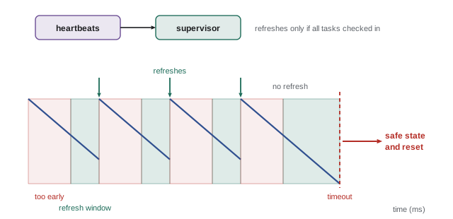
/* Supervisor: refresh the window watchdog only if all critical tasks checked in */
static volatile uint32_t heartbeat;            /* each task sets its own bit  */
#define HB_JOINT   (1u << 0)
#define HB_SAFETY  (1u << 1)
#define HB_COMMS   (1u << 2)
#define HB_ALL     (HB_JOINT | HB_SAFETY | HB_COMMS)

void supervisor_task(void *arg)                /* runs every 10 ms             */
{
    TickType_t last = xTaskGetTickCount();
    for (;;) {
        xTaskDelayUntil(&last, pdMS_TO_TICKS(10));
        uint32_t seen = __atomic_exchange_n(&heartbeat, 0, __ATOMIC_SEQ_CST);
        if (seen == HB_ALL) {
            WWDG->CR = WWDG_RELOAD;            /* refresh inside the window    */
        } else {
            enter_safe_state(seen ^ HB_ALL);   /* report which task is missing */
        }
    }
}
Worked problem
Setting a window watchdog
A supervisor runs every 10 ms with up to 1 ms of jitter. The watchdog clock gives 0.5 ms per count. Choose a timeout and an early-refresh limit, and give the worst-case time from a hang to safe state.
Show solution
- Refreshes arrive every 9 to 11 ms.
- Set the window to open at 8 ms (16 counts) and the timeout at 14 ms (28 counts), giving margin on both sides.
- If the system hangs just after a refresh, the timeout fires 14 ms later.
Answer: Window 8 to 14 ms after each refresh; worst-case detection time 14 ms. This detection time must be included in the robot's safety reaction time, alongside the time to remove motor power and the stopping distance.
Fault handling and safe states
Every robot needs a defined safe state for each failure, and the right one depends on the machine. For many arms it is removing motor power and applying brakes (a category 0 stop) or decelerating under control and then removing power (category 1); for some, controlled stopping with power maintained (category 2). For a drone, cutting power is the worst option in flight. Fault handlers should be designed with the same care as normal paths: a hard fault handler on a Cortex-M should log the faulting address and registers to a reserved memory area, put outputs into their safe condition and then reset, so that the cause can be diagnosed afterwards. Common detection mechanisms include range and plausibility checks on sensor values, comparing redundant sensors, deadline and overrun monitoring (lesson 4), stack and memory protection faults (lesson 8), CRCs on messages and stored data, and periodic self-tests of RAM, flash and the processor.
| Fault | Detection | Typical reaction |
|---|---|---|
| Control task overrun | Overrun counter, deadline monitor | Hold last output; stop if repeated |
| Hung task or deadlock | Supervisor and window watchdog | Safe state, then reset |
| Stuck or implausible sensor | Range, rate and redundancy checks | Switch to backup sensor or stop |
| Stale command stream | Timeout or middleware deadline | Decelerate to standstill |
| Memory corruption | MPU fault, CRC, stack guard | Log, safe state, reset |
| Communication errors | CRC, sequence counters, heartbeats | Retry within budget, then stop |
Testing real-time software
Testing real-time software combines ordinary software testing with tests of timing and fault behavior.
- Unit tests check functions on a host computer, with hardware access replaced by test doubles. Control algorithms, filters and state machines can be tested thoroughly this way, with coverage measured.
- Integration tests on the target exercise tasks together, with the real RTOS and drivers.
- Hardware-in-the-loop (HIL) testing connects the real controller to a real-time simulation of the robot and its environment, so that the firmware experiences realistic sensor signals and its outputs drive a simulated plant. HIL makes it possible to test dangerous faults, such as a broken encoder at full speed, safely and repeatably.
- Timing tests run long soaks under maximum load while recording maximum response times, overruns and stack high-water marks (lessons 2 and 8).
- Fault-injection tests deliberately cause the faults the design claims to handle: disconnect sensors, corrupt messages, stall tasks, fill queues, and check that each is detected and handled within its required time.
# Fault-injection test of a joint supervisor state machine (host-side)
class Supervisor:
    def __init__(self):
        self.state, self.missed = "RUN", 0
    def step(self, encoder_ok, cmd_age_ms, overrun):
        if self.state == "SAFE":
            return self.state
        if not encoder_ok:
            self.state = "SAFE"                      # immediate stop
        elif cmd_age_ms > 20:
            self.state = "STOPPING"                  # decelerate on stale command
        elif overrun:
            self.missed += 1
            if self.missed >= 3:
                self.state = "SAFE"                  # repeated overruns
        else:
            self.missed = 0
            if self.state == "STOPPING":
                self.state = "RUN"
        return self.state

tests = {
    "encoder fails":       [(True, 1, False)] * 3 + [(False, 1, False)],
    "commands stop":       [(True, a, False) for a in (1, 10, 25, 30)],
    "one overrun":         [(True, 1, x) for x in (False, True, False, False)],
    "three overruns":      [(True, 1, True)] * 3,
    "stale then resumes":  [(True, 30, False), (True, 2, False)],
}
expected = {"encoder fails": "SAFE", "commands stop": "STOPPING", "one overrun": "RUN",
            "three overruns": "SAFE", "stale then resumes": "RUN"}
fails = 0
for name, seq in tests.items():
    s = Supervisor()
    for inputs in seq:
        final = s.step(*inputs)
    ok = final == expected[name]
    fails += not ok
    print("%-20s -> %-8s %s" % (name, final, "pass" if ok else "FAIL"))
print("failures:", fails)encoder fails -> SAFE pass commands stop -> STOPPING pass one overrun -> RUN pass three overruns -> SAFE pass stale then resumes -> RUN pass failures: 0
Tests like these are cheap to run on every commit in continuous integration. The same scenarios are then repeated on HIL rigs with real timing, because a state machine that reacts correctly on a host may still react too slowly on the target.
Worked problem
How long must a soak test run?
A team wants reasonable evidence that a 2 kHz control loop overruns less than once per 10⁸ cycles. If it runs with no overruns, how long must the test last to have about 95 % confidence?
Show solution
- With zero failures in n trials, a 95 % upper bound on the failure rate is about \( 3/n \) (the rule of three).
- For a bound of \( 10^{-8} \): \( n = 3 \times 10^{8} \) cycles.
- At 2 kHz: \( 3 \times 10^{8} / 2000 = 150{,}000 \) s, about 42 hours.
Answer: About 42 hours of overrun-free running under worst-case load. Testing alone struggles to demonstrate very low failure rates, which is why analysis (lesson 5) and design measures are needed for hard deadlines.
Static analysis and code review
Static analysis tools examine source code without running it. Coding-standard checkers enforce MISRA C or similar rules (lesson 8); bug finders detect null dereferences, buffer overruns, uninitialized variables and data races; and sound analyzers based on abstract interpretation can prove the absence of whole classes of run-time errors, such as division by zero or array out-of-bounds, for every possible input. Worst-case stack and execution-time analyzers belong to the same family. Combined with peer code review and compiler warnings set to fail the build, static analysis catches many faults that testing would find late or never.
Functional safety standards
Functional safety means freedom from unacceptable risk due to a system failing to perform its safety functions correctly. It is governed by standards that set requirements for the whole life cycle, from hazard analysis to decommissioning, with more rigor required for higher risk. This course gives an awareness-level map only; safety-related robot software must be developed by people trained in the applicable standard, and certification is done with accredited assessment bodies.
- IEC 61508 is the generic standard for electrical, electronic and programmable safety systems. It defines four safety integrity levels, SIL 1 to SIL 4, each with targets for the probability of dangerous failure and requirements for development techniques, and part 3 covers software.
- ISO 13849-1, revised in 2023, covers safety-related parts of machine control systems. It rates safety functions by performance level, PL a to PL e, based on architecture category, component reliability, diagnostic coverage and common-cause failure measures. IEC 62061 is the machinery alternative based on SIL.
- ISO 10218-1 and -2, revised in 2025, are the safety standards for industrial robots and robot systems; the 2025 edition absorbed the collaborative-robot guidance of ISO/TS 15066 and is generally read as requiring PL d with category 3 architecture for key safety functions unless risk assessment justifies otherwise. ISO 13482 covers personal care robots and ISO 3691-4 driverless industrial trucks and mobile robots.
- ISO 26262 adapts IEC 61508 to road vehicles with automotive safety integrity levels, ASIL A to ASIL D, and is relevant to autonomous vehicles and many robot components derived from automotive parts.
- National adoption differs. In Canada, CSA Z434 adopts ISO 10218 with Canadian deviations, and provincial occupational health and safety rules and the Canadian Electrical Code apply to installations. In the United States, ANSI/A3 R15.06 (a 2025 edition adopting ISO 10218) is the national robot standard, while OSHA's general duty clause and machine guarding rules and the National Electrical Code apply to installations.
In software terms, higher integrity levels demand more: formal requirements and traceability, restricted language subsets, defensive programming, full structural test coverage, independent review, qualified tools, and freedom from interference, meaning evidence that less critical software cannot disturb safety functions through memory, timing or communication. The memory protection of lesson 8, the timing analysis of lesson 5 and the supervisors of this lesson are the technical means of providing that evidence. A common architecture keeps safety functions on a separate, certified safety controller or safety-rated drive functions such as safe torque off, so that the large non-safety software stack does not need certification at all.
Worked problem
Reaction time and stopping distance
A mobile robot moving at 1.5 m/s must stop before reaching a person detected by a safety laser scanner. The scanner's response time is 60 ms, the safety controller adds 20 ms, the brakes take 50 ms to engage and then decelerate the robot at 2 m/s². How far does the robot travel from detection to standstill?
Show solution
- Delay before braking: \( 60 + 20 + 50 = 130 \) ms, covering \( 1.5 \times 0.13 = 0.195 \) m.
- Braking distance: \( v^2/(2a) = 2.25/4 = 0.5625 \) m.
- Total: \( 0.195 + 0.5625 = 0.76 \) m.
Answer: About 0.76 m, so the protective field must extend at least that far plus the margins required by the applicable standard. Every millisecond of software reaction time adds 1.5 mm of stopping distance at this speed.
Security and safety together
A robot connected to a network is open to attack, and an attacker who can change firmware or commands can defeat every safety measure that depends on software. Security is now treated alongside safety. IEC 62443 is the industrial automation security series, defining security levels and requirements for components and systems. Practical measures for embedded robot controllers include secure boot, which verifies a cryptographic signature on firmware before running it; signed and encrypted firmware updates with rollback protection; disabling or locking debug ports in production; authenticated and integrity-checked messages on networks that cross trust boundaries; and keeping safety functions on hardware that does not accept remote software changes at all. Regulation is tightening: the European Union's Cyber Resilience Act and Machinery Regulation, both phasing in during 2026 and 2027, add cybersecurity obligations for products with digital elements and for machinery sold in Europe, which affects Canadian and US robot makers who export.
Common mistakes
MistakeRefreshing the watchdog from a timer interrupt
InsteadRefresh only from a supervisor that checks every critical task's heartbeat.
MistakeLeaving safe states undefined for some faults
InsteadDefine and test a safe reaction and its timing for each failure mode.
MistakeRelying on short tests to show rare failures are absent
InsteadCombine long soaks with analysis, using the rule of three to size tests.
MistakeTesting only the normal paths
InsteadInject faults deliberately in unit, HIL and system tests.
MistakeKeeping debug ports open and firmware unsigned in production
InsteadUse secure boot, signed updates and locked debug interfaces.
Summary and key terms
- Faults cause errors that may become failures, and good design prevents, detects and contains them at each step.
- Window watchdogs refreshed by a supervisor detect hung and runaway software within a bounded time.
- Each failure needs a defined safe state, which depends on the machine and its stop category.
- Testing spans host unit tests, target integration, hardware-in-the-loop, long timing soaks and fault injection.
- The rule of three shows that demonstrating very low failure rates by testing alone needs very long runs.
- IEC 61508, ISO 13849-1, ISO 10218 and ISO 26262 set life-cycle requirements scaled to risk, with national adoption through CSA and ANSI.
- Security measures such as secure boot and signed updates protect the software that safety depends on.
- Fault
- A defect or abnormal condition that can cause an error.
- Failure
- Delivered behavior that deviates from what was required.
- Watchdog timer
- A hardware timer that triggers a reset or safe state unless refreshed.
- Window watchdog
- A watchdog that also faults if refreshed too early.
- Safe state
- A condition the system enters on a fault in which risk is acceptable.
- Hardware-in-the-loop
- Testing a real controller against a real-time simulation of its plant.
- Fault injection
- Deliberately causing faults to test detection and reaction.
- SIL
- Safety integrity level, 1 to 4, defined in IEC 61508.
- Performance level
- A rating from PL a to PL e for machine safety functions under ISO 13849-1.
- Secure boot
- Verifying a firmware signature before allowing it to run.
Practice problems
Work each problem on paper first, then reveal the answer to check.
Distinguish a fault from a failure.
Show answer
A fault is a defect; a failure is wrong delivered behavior.
Why is refreshing a watchdog from a timer interrupt weak?
Show answer
It only proves the interrupt runs, not the tasks.
What extra fault does a window watchdog catch?
Show answer
Refreshing too early, such as a tight runaway loop.
A loop runs 10⁷ cycles without failure. What 95 % bound does the rule of three give?
Show answer
\( 3 \times 10^{-7} \) per cycle.
What does HIL testing let you test safely?
Show answer
Dangerous faults with realistic signals and timing.
Which standard defines PL a to PL e?
Show answer
ISO 13849-1.
Which standard did the 2025 ISO 10218 absorb?
Show answer
ISO/TS 15066 on collaborative robots.
What is the Canadian adoption of ISO 10218?
Show answer
CSA Z434.
At 2 m/s, how far does a robot travel in 100 ms of reaction time?
Show answer
0.2 m.
Name two embedded security measures.
Show answer
Secure boot and signed firmware updates (also locked debug ports).
Lesson quiz · 5 questions
Score 60% or more to complete this lesson.
Create a free account to save your progress, take quizzes and earn a certificate.