
ROB-320 · Lesson 3 of 12 · 29 min
Bare-metal architectures: super-loops, interrupts and cooperative schedulers
Not every real-time system needs an operating system. A great deal of robot firmware, from servo drives to battery managers to sensor modules, runs bare metal: the program owns the whole processor, starts at reset and never hands control to a kernel. Bare-metal code can be simple, fast and easy to analyze, but only if it is organized well. This lesson covers the main bare-metal patterns, from the plain super-loop to interrupt-driven designs and cooperative schedulers, with their timing behavior and the point at which an RTOS (lesson 4) becomes the better choice. ROB-200 introduced timers, interrupts and the non-blocking blink; here the focus is on structuring a whole program so that its timing can be predicted.
The super-loop
The simplest structure is an infinite loop that calls each job in turn: read sensors, update the controller, service communications, update the display, repeat. It needs no scheduler and no shared-data protection, because only one thing runs at a time. Its timing, however, is fragile. The time between two runs of the controller is the sum of every job's execution time in that pass, so it varies whenever any job's time varies, and adding a feature anywhere changes the control rate everywhere. A slow job, such as writing a block to flash, delays everything behind it.
int main(void)
{
    init_hardware();
    for (;;) {                  /* super-loop: one pass after another */
        read_sensors();
        run_controller();       /* period = sum of all job times      */
        service_uart();
        update_leds();
    }
}
The worst-case time between two controller runs is the sum of the worst cases of all jobs in the loop. The jitter is the difference between the longest and shortest passes. Both are easy to calculate, which is the super-loop's real virtue, and for a small sensor module with three jobs and generous deadlines it may be exactly the right answer.
Worked problem
Super-loop period and jitter
A super-loop runs four jobs with best and worst execution times (µs) of: sensors 40 and 60, controller 90 and 150, UART 5 and 400, LEDs 10 and 10. What are the shortest and longest loop periods, and the jitter seen by the controller?
Show solution
- Shortest pass: \( 40 + 90 + 5 + 10 = 145 \) µs.
- Longest pass: \( 60 + 150 + 400 + 10 = 620 \) µs.
- Jitter: \( 620 - 145 = 475 \) µs.
Answer: The controller runs every 145 to 620 µs, a jitter larger than its own execution time. The UART job, which occasionally processes a long message, is the main culprit; making it process a bounded number of bytes per pass would cut the longest pass sharply.
Fixing the rate: timer-triggered loops
The first improvement is to make the loop wait for a timer tick before each pass. A hardware timer sets a flag every millisecond; the loop spins or sleeps until the flag is set, clears it and runs its jobs. The control period is now fixed by the timer, and jitter falls to the variation in when the loop notices the flag. The cost is that the whole pass must fit in one tick. If it overruns, the next tick is missed or taken late, so the design must check for overruns and count them.
A common extension runs different jobs at different multiples of the base tick: the controller every tick, communications every fifth tick, the display every hundredth. This is a static cyclic executive, the oldest real-time scheduling method and still widely used in avionics, where it is valued because its timeline can be printed and checked by hand. The designer arranges jobs into minor frames (one tick each) inside a major frame (the repeating pattern), splitting long jobs so that no minor frame overruns.
# Build and check a cyclic executive table (minor frame = 1 ms)
jobs = {"control": (1, 0.30), "comms": (5, 0.25), "logger": (10, 0.40),
        "display": (20, 0.35)}               # name: (period in frames, C in ms)
major = 20
frames = [[] for f in range(major)]
offset = {"control": 0, "comms": 1, "logger": 2, "display": 3}
for name, (period, C) in jobs.items():
    for f in range(offset[name], major, period):
        frames[f].append(name)
worst = 0.0
for f, names in enumerate(frames):
    load = sum(jobs[n][1] for n in names)
    worst = max(worst, load)
    if f < 6 or load > 0.9:
        print("frame %2d: %-30s %.2f ms" % (f, "+".join(names), load))
print("worst frame load: %.2f ms of 1.00 ms" % worst)
U = sum(C / p for p, C in jobs.values())
print("average utilization: %.3f" % U)frame 0: control 0.30 ms frame 1: control+comms 0.55 ms frame 2: control+logger 0.70 ms frame 3: control+display 0.65 ms frame 4: control 0.30 ms frame 5: control 0.30 ms worst frame load: 0.70 ms of 1.00 ms average utilization: 0.407
With the offsets chosen, no minor frame holds more than the controller and one other job, so the worst frame uses well under the 1 ms available even though the average utilization is modest. Putting all the slow jobs at offset 0 would stack them into the same frame and overrun it, which is why offsets are the main design lever in a cyclic executive.
Interrupt-driven designs
In an interrupt-driven design, time-critical work runs in interrupt service routines triggered directly by hardware events, and the main loop handles everything else in the background. The control loop runs in the timer interrupt, so its start time is fixed by hardware and does not depend on what the background is doing; only interrupt latency and higher-priority interrupts can delay it. This foreground-background pattern is the workhorse of motor control firmware: the current loop runs in the ADC-complete interrupt at 20 kHz, the speed loop in a lower-priority timer interrupt at 1 kHz, and the main loop handles communications and diagnostics.
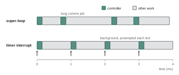
Interrupt-driven designs need discipline. Interrupt routines should be short and bounded, because while one runs, lower-priority interrupts and the background wait. Data shared between an interrupt and the background must be protected (lesson 7). And the interrupt priorities must be chosen deliberately, with the most urgent and shortest work at the highest priority. Nested vectored interrupt controllers such as the ARM NVIC make this a priority-based preemptive scheduler implemented in hardware, and the response-time analysis of lesson 5 applies to interrupts just as it does to RTOS tasks.
Worked problem
Background throughput under interrupt load
A drive runs a 20 kHz current-loop interrupt taking 12 µs and a 1 kHz speed-loop interrupt taking 80 µs. What fraction of the processor is left for the background loop, and how long will a 3 ms background job take to complete?
Show solution
- Current loop share: \( 12 / 50 = 0.24 \).
- Speed loop share: \( 80 / 1000 = 0.08 \).
- Background share: \( 1 - 0.32 = 0.68 \).
- Elapsed time for 3 ms of background work: about \( 3 / 0.68 = 4.4 \) ms.
Answer: About 68 % of the processor remains, so a 3 ms background job takes roughly 4.4 ms of wall-clock time. Background deadlines must be checked against elapsed time, not execution time.
Deferring work out of interrupts
Keeping interrupts short often means splitting a job: the interrupt does the urgent part, such as copying a received byte or latching a sensor value, and sets a flag or queues an item for the background to finish. This pattern goes by many names, including top half and bottom half in Linux and deferred procedure calls in Windows. In bare-metal code it is usually a set of event flags or a small queue checked by the main loop. The design question is how long deferred work may wait. If the background loop's longest pass is 620 µs, deferred work may wait that long, which is fine for logging but not for a safety response.
Cooperative schedulers
Between the super-loop and a full RTOS sits the cooperative scheduler. Each job is written as a short function that does a bounded piece of work and returns. A small scheduler, often a table of function pointers with periods and next-run times, calls each job when it is due. Jobs never block; a job that needs to wait, say for an I2C transfer, returns and is called again later, keeping its progress in a state variable. This is the run-to-completion or event-loop style, and it is how many embedded frameworks, Arduino-style libraries and the main loops of single-threaded robot nodes work.
typedef struct { void (*fn)(void); uint32_t period_ms, next_ms; } job_t;

static job_t jobs[] = {
    { control_step,  1, 0 },
    { comms_step,    5, 1 },
    { battery_step, 100, 2 },
};

void scheduler_run(void)
{
    for (;;) {
        uint32_t now = millis();
        for (size_t i = 0; i < sizeof jobs / sizeof jobs[0]; i++) {
            if ((int32_t)(now - jobs[i].next_ms) >= 0) {
                jobs[i].next_ms += jobs[i].period_ms;   /* absolute, no drift */
                jobs[i].fn();                           /* must return quickly */
            }
        }
        __WFI();                                        /* sleep until next interrupt */
    }
}
Advancing next_ms by the period, rather than setting it to now plus the period, keeps the schedule anchored to absolute time so that small delays do not accumulate into drift. The cooperative scheduler's weakness is that a job can be delayed by the longest job ahead of it, because nothing can preempt a running job. Its worst-case latency is therefore the longest single job, not the longest pass of the whole loop, which is an improvement over the super-loop but still means every job must be written to be short.
Long operations are broken into steps using a state machine. A job that writes a 4 kB block to flash might erase in one call, then program 256 bytes per call over 16 calls, returning in between. This keeps latency low at the cost of more complex code, which is the main reason designers eventually move to an RTOS, where a task can be written as straight-line code that blocks while waiting and the kernel switches to other work.
Worked problem
Splitting a long job
A cooperative scheduler runs a 1 ms control job taking 200 µs. A logging job must write 4 kB to flash; programming takes 18 µs per 64-byte row plus 10 µs overhead per call. How many rows can the logging job write per call if the control job must never wait more than 300 µs?
Show solution
- The logging call may last at most 300 µs.
- Rows per call: \( (300 - 10) / 18 = 16.1 \), so 16 rows (1 kB) per call.
- A 4 kB block needs \( 64 / 16 = 4 \) calls.
Answer: Write 16 rows per call, finishing a 4 kB block in four calls. Each call lasts about 298 µs, keeping the control job's worst wait under 300 µs.
Choosing an architecture
| Architecture | Strengths | Weaknesses | Typical use |
|---|---|---|---|
| Super-loop | Simplest; no shared-data issues | Period and jitter depend on every job | Tiny sensors, prototypes |
| Timer-triggered loop or cyclic executive | Fixed period; timeline can be checked by hand | Every frame must fit; hard to change | Avionics, small safety controllers |
| Foreground-background (interrupt-driven) | Low latency for urgent work; hardware priorities | Shared data needs care; background starved under load | Motor drives, sensor front ends |
| Cooperative scheduler | Several rates; no preemption issues | Latency equals longest job; long work must be split | Event-driven firmware, single-threaded nodes |
| Preemptive RTOS (lesson 4) | Straight-line blocking code; priorities; services | Kernel overhead; concurrency bugs possible | Robot controllers with many functions |
The right choice depends on how many independent activities there are, how different their timing needs are and how often the firmware will change. A servo drive with one hard loop and some communications is well served by foreground-background. A mobile robot's base controller, juggling motor control, odometry, battery management, a CAN link, a USB link to the main computer and an LED status display, usually benefits from an RTOS. Whatever the choice, document it: the architecture decides how every later timing question is answered.
Common mistakes
MistakeAdding features to a super-loop without re-checking the control period
InsteadBound every job, or move the controller into a timer interrupt.
MistakeDoing slow work such as printing inside an interrupt routine
InsteadKeep interrupts short and defer the rest to background code.
MistakeScheduling the next run as now plus the period
InsteadAdvance the next release time by the period to avoid drift.
MistakeLetting a cooperative job run until its work is finished
InsteadSplit long work into bounded steps with a state machine.
MistakeStacking every slow job in the same cyclic-executive frame
InsteadChoose offsets so each minor frame stays within budget.
Summary and key terms
- Bare-metal firmware owns the processor and can be simple and predictable if well structured.
- A super-loop's period and jitter depend on every job in the loop.
- A timer-triggered loop or cyclic executive fixes the period, but every frame must fit within one tick.
- Interrupt-driven designs run urgent work in hardware-triggered routines and leave the rest to a background loop.
- Interrupt routines must be short, with longer work deferred through flags or queues.
- Cooperative schedulers call short run-to-completion jobs at set rates, so latency equals the longest job.
- An RTOS becomes worthwhile when there are many activities with different rates and blocking waits.
- Bare metal
- Firmware that runs directly on the hardware without an operating system.
- Super-loop
- An infinite loop that calls each job in turn.
- Cyclic executive
- A static schedule of jobs laid out in minor frames within a repeating major frame.
- Minor frame
- One base tick of a cyclic executive.
- Major frame
- The repeating pattern of minor frames in a cyclic executive.
- Foreground-background
- A design with urgent work in interrupts and other work in a main loop.
- Deferred work
- Processing moved out of an interrupt to run later in lower-priority code.
- Cooperative scheduler
- A scheduler that runs jobs to completion without preemption.
- Run to completion
- A job style in which each call does bounded work and returns.
- Drift
- Gradual accumulation of timing error when releases are timed relative to previous runs.
Practice problems
Work each problem on paper first, then reveal the answer to check.
A super-loop has worst-case job times 30, 120, 250 and 15 µs. What is the worst period?
Show answer
415 µs.
Why does a timer-triggered loop reduce jitter?
Show answer
The timer fixes the start of each pass.
A 10 kHz interrupt takes 30 µs. What share does it use?
Show answer
30 %.
In a cooperative scheduler, what bounds a job's waiting time?
Show answer
The longest single job.
Name the Linux term for deferred interrupt work.
Show answer
Bottom half.
What is a major frame?
Show answer
The repeating pattern of minor frames in a cyclic executive.
Why advance next_ms by the period rather than set it to now plus period?
Show answer
To avoid accumulated drift.
If background has 60 % of the processor, how long does 1.2 ms of background work take?
Show answer
About 2 ms.
What design pattern splits flash writing into small calls?
Show answer
A state machine in a run-to-completion job.
Give one sign that a project has outgrown bare metal.
Show answer
Many activities with different rates and blocking waits.
Lesson quiz · 5 questions
Score 60% or more to complete this lesson.
Create a free account to save your progress, take quizzes and earn a certificate.