
ROB-330 · Lesson 2 of 12 · 31 min
Image formation and the pinhole camera model
To measure the world with a camera, a robot needs a mathematical model of how points in 3-D space end up at particular pixels. That model is the bridge between image coordinates, which detectors produce, and metric coordinates, which planners and controllers need. The pinhole camera model, refined with a description of lens distortion, is accurate to a fraction of a pixel for most robot cameras and underlies almost everything in the rest of this course: calibration, stereo, visual odometry, pose estimation and point clouds. This lesson builds the model one step at a time, from a single point to the full projection matrix, and shows how to run it backwards to turn a pixel into a ray in space.
The pinhole and similar triangles
Imagine a light-tight box with a tiny hole in one face. Light from each point in the scene passes through the hole in a straight line and lands on the back wall, forming an inverted image. A real lens gathers far more light than a pinhole, but for a lens focused at a distance much greater than its focal length, the geometry is the same: every ray passes through a single point, the center of projection or optical center.
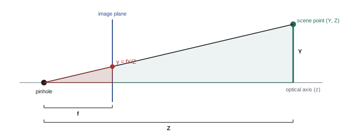
Place a coordinate frame at the optical center with the z axis pointing out along the optical axis into the scene, x to the right and y down (the usual computer-vision convention, chosen so that y increases down the image like pixel rows). A scene point at \( (X, Y, Z) \) in this camera frame projects onto an image plane at distance f in front of the center, at
This follows from similar triangles: the image is smaller than the object by the ratio of f to Z. Two consequences matter constantly in robotics. First, size in the image falls as 1/Z, so an object twice as far away looks half as big. Second, depth is lost: every point along the ray through the optical center lands on the same image point, so a single image cannot tell a small near object from a large far one. Recovering depth needs extra information, such as a second camera (lesson 6), motion (lesson 7), a known object size, or an active depth sensor.
Worked problem
How big does an object look?
A camera with a 6 mm lens views a 300 mm-tall box 2 m away. How tall is its image on the sensor? If the sensor's pixels are 3 µm square, how many pixels tall is the box?
Show solution
- Image height: \( y = f \, Y/Z = 6 \times 300/2000 = 0.9 \) mm.
- In pixels: \( 0.9 \text{ mm} \div 0.003 \text{ mm/px} = 300 \) px.
Answer: The box is 0.9 mm tall on the sensor, about 300 pixels. At 4 m it would be about 150 pixels.
From millimeters to pixels: the intrinsic matrix
Detectors report positions in pixels, not millimeters, so the model needs two more steps. Divide by the pixel size to convert to pixel units, which gives the focal length in pixels: \( f_x = f/s_x \) and \( f_y = f/s_y \), where \( s_x \) and \( s_y \) are the pixel width and height. Then shift the origin from the optical axis to the top-left corner of the image, by adding the principal point \( (c_x, c_y) \), the pixel where the optical axis meets the sensor. The result is
Written with homogeneous coordinates, the whole mapping becomes one matrix multiplication followed by division by the third component:
Here \( \lambda = Z \) is the scale factor removed by the division. K is the intrinsic matrix, and its parameters are the camera's intrinsics: they depend only on the camera and lens, not on where the camera is. The skew s is zero for virtually all modern sensors. For square pixels \( f_x \approx f_y \), and the principal point is usually within a few tens of pixels of the image center but should never be assumed to be exactly there.
The focal length in pixels links directly to field of view. For an image W pixels wide, the horizontal field of view is
Worked problem
Focal length in pixels and field of view
A 1280 × 1024 sensor has 4.8 µm pixels behind an 8 mm lens. Find \( f_x \) and the horizontal field of view.
Show solution
- \( f_x = 8 \text{ mm} / 0.0048 \text{ mm} = 1667 \) px.
- FOV: \( 2\arctan(640/1667) = 2 \times 21.0^{\circ} = 42.0^{\circ} \).
Answer: About 1667 pixels and a 42° horizontal field of view. A 4 mm lens on the same sensor would give about 75°.
Where is the camera? Extrinsics
Points in the world are usually described in some other frame: the robot base, a map, or a work cell. The extrinsic parameters, a rotation R and translation t, transform a world point \( \mathbf{P}_w \) into the camera frame:
These are exactly the rigid-body transforms of ROB-210, and the same care with frame names applies: R and t here take world coordinates into camera coordinates, which is the inverse of the camera's pose in the world. Combining extrinsics and intrinsics gives the 3 × 4 camera projection matrix
P has 11 independent parameters: 5 intrinsic (with skew) and 6 extrinsic (3 for rotation, 3 for translation). On a robot the extrinsics come from the kinematic chain plus a calibrated camera mounting transform, often published in ROS 2 as a tf frame such as camera_optical_frame. Note that ROS distinguishes the camera body frame (x forward) from the optical frame (z forward, x right, y down) used in this lesson; mixing them up rotates every result by 90°.
import numpy as np

K = np.array([[800.0, 0, 320],
              [0, 800.0, 240],
              [0, 0, 1]])

# camera 1.2 m above the floor looking straight down: world z up, camera z down
R = np.array([[1.0, 0, 0],
              [0, -1.0, 0],
              [0, 0, -1.0]])
cam_pos = np.array([0.0, 0.0, 1.2])          # camera position in world frame
t = -R @ cam_pos                              # world -> camera translation

P = K @ np.hstack([R, t.reshape(3, 1)])

pts_w = np.array([[0.0, 0.0, 0.0],            # floor point under the camera
                  [0.3, 0.2, 0.0],            # floor point offset
                  [0.3, 0.2, 0.4]])           # top of a 0.4 m box at the same x, y
for Pw in pts_w:
    h = P @ np.append(Pw, 1.0)
    u, v = h[:2] / h[2]
print("world", Pw, "-> pixel (%.1f, %.1f), depth %.2f m" % (u, v, h[2]))world [0. 0. 0.] -> pixel (320.0, 240.0), depth 1.20 m world [0.3 0.2 0. ] -> pixel (520.0, 106.7), depth 1.20 m world [0.3 0.2 0.4] -> pixel (620.0, 40.0), depth 0.80 m
The box top projects farther from the image center than the floor point directly below it, because it is closer to the camera. This parallax is a depth cue, and it also means that a downward camera cannot measure x and y positions on top of objects without knowing their height.
Running the model backwards: pixels to rays
Many robot tasks need the inverse: given a pixel, where in space could the point be? Inverting the intrinsics gives the ray direction in the camera frame,
and every point \( Z\,\mathbf{d} \) for \( Z > 0 \) projects to that pixel. If the depth is known, from a depth camera or by intersecting the ray with a known plane such as the floor or a table, the 3-D point follows. This back-projection is how a depth image becomes a point cloud (lesson 8) and how a robot picking from a flat conveyor turns a detected pixel into a grasp position.
Worked problem
Locating a part on a table
A camera looks straight down at a table 0.80 m below its optical center. Its intrinsics are \( f_x = f_y = 900 \), \( c_x = 640 \), \( c_y = 360 \). A detector finds a part's center at pixel (865, 480). Where is the part in the camera frame?
Show solution
- Ray: \( x = (865 - 640)/900 = 0.250 \), \( y = (480 - 360)/900 = 0.133 \).
- Scale by depth Z = 0.80 m: \( X = 0.250 \times 0.80 = 0.200 \) m, \( Y = 0.133 \times 0.80 = 0.107 \) m.
Answer: The part is at about (0.200, 0.107, 0.800) m in the camera frame. The camera-to-robot transform then gives the grasp position in the robot base frame.
Lens distortion
Real lenses bend straight lines, especially near the edges of the image and especially with wide-angle lenses. Radial distortion moves points toward or away from the image center by an amount that grows with distance from it: barrel distortion (lines bow outwards) is typical of wide lenses, and pincushion distortion (lines bow inwards) of some telephoto lenses. Tangential distortion arises when the lens is not perfectly parallel to the sensor. The widely used Brown–Conrady model applies these corrections in normalized coordinates \( (x, y) \), with \( r^2 = x^2 + y^2 \):
with a matching expression for \( y_d \). The coefficients \( k_1, k_2, k_3 \) (radial) and \( p_1, p_2 \) (tangential) are found during calibration (lesson 3) and stored with the intrinsics; OpenCV and ROS camera_info messages call this the plumb_bob model. Fisheye lenses with fields of view near or beyond 180° need a different model, such as the equidistant model \( r_d = f\theta \), because the pinhole equation cannot represent rays more than 90° off axis.
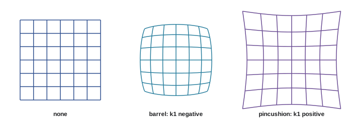
In practice, robot software usually undistorts images, or undistorts just the detected feature points, before applying pinhole geometry. Undistorting points is far cheaper than undistorting whole images and avoids resampling blur, so many pose estimation and odometry systems detect features in the raw image and correct only their coordinates.
Worked problem
How large is the distortion?
A wide-angle camera has \( k_1 = -0.28 \), \( k_2 = 0.08 \), other coefficients zero, and \( f_x = 600 \). How far, in pixels, is a point at normalized radius r = 0.5 moved?
Show solution
- Factor: \( 1 + k_1 r^2 + k_2 r^4 = 1 - 0.28(0.25) + 0.08(0.0625) = 1 - 0.07 + 0.005 = 0.935 \).
- Distorted radius: \( 0.5 \times 0.935 = 0.4675 \).
- Shift: \( (0.5 - 0.4675) \times 600 = 19.5 \) px toward the center.
Answer: About 20 pixels, an enormous error for measurement. Ignoring distortion on a wide lens would ruin any metric result near the edges of the image.
Common mistakes
MistakeAssuming the principal point is exactly at the image center
InsteadUse the calibrated \( c_x, c_y \), which commonly differ by tens of pixels.
MistakeMixing up the camera body frame and the optical frame in ROS
InsteadCheck frame conventions: the optical frame has z forward, x right and y down.
MistakeUsing the world-to-camera transform as if it were the camera's pose
InsteadRemember that \( [R\,|\,t] \) maps world points into the camera; the camera's pose is its inverse.
MistakeApplying pinhole geometry to raw pixels from a wide-angle lens
InsteadUndistort points or images with the calibrated distortion model first.
MistakeExpecting one image to give the depth of an unknown object
InsteadAdd depth from a second view, motion, a known size, a known plane or a depth sensor.
Summary and key terms
- The pinhole model projects \( (X, Y, Z) \) to \( (fX/Z, fY/Z) \); image size falls as 1/Z and depth is lost.
- The intrinsic matrix K holds focal lengths in pixels, the principal point and skew.
- Field of view follows from \( 2\arctan(W/2f_x) \).
- Extrinsics R and t take world points into the camera frame, and \( P = K[R\,|\,t] \) has 11 parameters.
- Back-projection with \( K^{-1} \) turns a pixel into a ray; a known depth or plane fixes the 3-D point.
- Radial and tangential distortion are modeled with the Brown–Conrady coefficients; fisheye lenses need their own model.
- Undistorting feature points is cheaper and sharper than undistorting whole images.
- Optical center
- The point through which all rays pass in the pinhole model.
- Principal point
- The pixel where the optical axis meets the image.
- Intrinsics
- Camera parameters independent of position: focal lengths, principal point, skew and distortion.
- Extrinsics
- The rotation and translation from a world frame into the camera frame.
- Projection matrix
- The 3 × 4 matrix \( K[R\,|\,t] \) mapping homogeneous world points to pixels.
- Homogeneous coordinates
- Coordinates with an extra component that make projection a matrix product.
- Back-projection
- Mapping a pixel to the ray of 3-D points that project to it.
- Radial distortion
- Lens distortion that moves points along lines through the image center.
- Barrel distortion
- Radial distortion that bows straight lines outward.
- Optical frame
- The camera frame with z along the optical axis, x right and y down.
Practice problems
Work each problem on paper first, then reveal the answer to check.
An object 1 m tall is 5 m away from a camera with f = 10 mm. How tall is its image?
Show answer
2 mm.
A 5 mm lens and 2 µm pixels: what is \( f_x \)?
Show answer
2500 px.
A 1920-pixel-wide image with \( f_x = 960 \): what is the horizontal FOV?
Show answer
90°.
How many parameters does a general projection matrix have?
Show answer
Eleven.
Write the ray direction for pixel \( (c_x, c_y) \).
Show answer
(0, 0, 1), along the optical axis.
Which sign of \( k_1 \) gives barrel distortion?
Show answer
Negative.
If an object moves from 2 m to 6 m away, by what factor does its image shrink?
Show answer
Three.
What extra information can recover depth from images?
Show answer
A second view, motion, known size, a known plane or a depth sensor.
Why undistort points rather than whole images?
Show answer
It is cheaper and avoids resampling blur.
What model suits a 185° fisheye lens?
Show answer
A fisheye model such as equidistant, not the pinhole model.
Lesson quiz · 5 questions
Score 60% or more to complete this lesson.
Create a free account to save your progress, take quizzes and earn a certificate.