
ROB-450 · Lesson 4 of 12 · 26 min
IEC 62061, IEC 61508 and validating safety functions
ISO 13849-1 is not the only route to a functionally safe machine. IEC 62061, Safety of machinery: Functional safety of safety-related control systems, expresses reliability as safety integrity levels (SILs) rather than performance levels, and it descends from IEC 61508, the basic functional safety standard for electrical, electronic and programmable electronic systems used across industries. Engineers working on robots meet all three: ISO 13849-1 for most machine safeguarding, IEC 62061 for complex programmable systems and drives, and IEC 61508 behind the safety-rated components they buy, such as safety PLCs, drives with safe torque off and robot controllers with safety-rated monitoring. This lesson explains the SIL approach, compares it with performance levels, and then covers what both standards require after design: verification, validation, periodic testing and management of modifications. It ends with the open problem of machine learning in safety functions.
IEC 61508 in brief
IEC 61508, first published in the late 1990s with its second edition in 2010 and a third edition in preparation at the time of writing, sets out a safety life cycle from concept through hazard and risk analysis, safety requirements, design, installation, operation, modification and decommissioning. It introduces four safety integrity levels, SIL 1 to SIL 4, each corresponding to a target range of failure measures. For safety functions demanded frequently or continuously, as on machines, the measure is the average frequency of dangerous failure per hour (PFH). For low-demand functions, such as emergency shutdown in a chemical plant, it is the average probability of failure on demand (PFDavg). Machinery almost always uses the high-demand or continuous mode.
| SIL | PFH range (per hour), high demand | Comparable PL in ISO 13849-1 |
|---|---|---|
| No SIL | 10^-5 to under 10^-4 | PL a |
| SIL 1 | 10^-6 to under 10^-5 | PL b and PL c |
| SIL 2 | 10^-7 to under 10^-6 | PL d |
| SIL 3 | 10^-8 to under 10^-7 | PL e |
| SIL 4 | 10^-9 to under 10^-8 | Not used in machinery |
IEC 61508 also requires measures against systematic failures, which are failures caused by errors in specification, design, manufacture or software rather than random hardware failures. A SIL claim therefore combines a quantitative target for random failures, architectural constraints that require a minimum level of fault tolerance or diagnostics, and qualitative requirements on development processes whose rigor increases with SIL. Component manufacturers who certify a safety PLC or drive to IEC 61508 provide a safety manual stating the SIL capability, the PFH of the component and the conditions of use, such as proof-test intervals and required diagnostics. System designers must follow those conditions, or the claim does not carry over.
IEC 62061: SIL for machinery
IEC 62061 applies the IEC 61508 approach to machinery, and its 2021 edition extended its scope from electrical systems to safety-related control systems of all technologies, which brings it closer to ISO 13849-1. Many companies choose one standard for consistency, often ISO 13849-1 for simpler functions and IEC 62061 for complex programmable systems, and the two standards' authors have worked to make the results comparable.
The required SIL is determined from a matrix rather than a risk graph. The severity of the consequence (Se) is scored from 1 for reversible injury needing first aid to 4 for irreversible injury such as death or the loss of an eye or arm. A class value (Cl) is the sum of three scores for the probability of harm: frequency and duration of exposure (Fr), probability of occurrence of the hazardous event (Pr) and possibility of avoiding or limiting harm (Av). The intersection of Se and Cl in the standard's matrix gives the required SIL or indicates that other measures are sufficient.
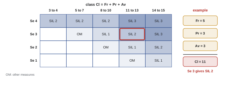
| Parameter | Scores used in the matrix |
|---|---|
| Severity Se | 4 irreversible: death, loss of eye or arm; 3 irreversible: broken limb, loss of finger; 2 reversible needing medical attention; 1 reversible needing first aid |
| Frequency Fr | 5 for exposure at intervals of a day or less; 4 up to two weeks; 3 up to a year; 2 more than a year |
| Probability Pr | 5 very high; 4 likely; 3 possible; 2 rarely; 1 negligible |
| Avoidance Av | 5 impossible; 3 possible; 1 likely |
Worked problem
Required SIL for a robot cell access point
An operator enters a palletizing cell several times a shift to remove damaged cartons. Contact with the moving robot could break a limb. Unexpected motion is judged possible, and avoidance possible because the robot is visible and moves at moderate speed near the pallet. Determine Se, Cl and the required SIL using the summarized matrix.
Show solution
- Severity: broken limb, irreversible, so Se = 3.
- Frequency: several times a shift, intervals under a day, so Fr = 5.
- Probability: possible, so Pr = 3. Avoidance: possible, so Av = 3.
- Class: \( \mathrm{Cl} = 5 + 3 + 3 = 11 \).
- Se 3 with Cl 11 to 13 gives SIL 2 in the matrix, comparable to PL d.
Answer: SIL 2 is required, matching the PL d that the ISO 13849-1 risk graph would typically give for similar parameters.
Building subsystems to a SIL
In IEC 62061 a safety function is decomposed into subsystems, such as sensing, logic and actuation, and the PFH values of the subsystems are added, just as PFHd values are added in ISO 13849-1. Each subsystem must also satisfy architectural constraints, which limit the SIL that can be claimed based on its hardware fault tolerance (HFT) and safe failure fraction (SFF). HFT is the number of faults a subsystem can tolerate without losing the function: a single channel has HFT 0, a redundant pair HFT 1. SFF is the fraction of failures that are either safe or dangerous but detected.
| Safe failure fraction | HFT 0 | HFT 1 | HFT 2 |
|---|---|---|---|
| Under 60 percent | Not allowed | SIL 1 | SIL 2 |
| 60 to under 90 percent | SIL 1 | SIL 2 | SIL 3 |
| 90 to under 99 percent | SIL 2 | SIL 3 | SIL 3 |
| 99 percent or more | SIL 3 | SIL 3 | SIL 3 |
For subsystems built from components rather than bought as certified units, IEC 62061 gives simplified formulas for four basic architectures. For a redundant subsystem with diagnostics, the common cause failure factor \( \beta \), typically between 1 and 10 percent depending on the measures taken against common causes, often dominates the result. A simplified form of the formula for two identical channels, each with dangerous failure rate \( \lambda_D \), diagnostic coverage DC, diagnostic test interval \( T_2 \) and proof-test interval or lifetime \( T_1 \), is shown below.
# PFH of a two-channel subsystem with diagnostics (IEC 62061 style, simplified)
import math
HOURS_PER_YEAR = 8760
def lam_from_mttfd(years):
    return 1 / (years * HOURS_PER_YEAR)
def pfh_redundant(lam, dc, t2_h, t1_h, beta):
    indep = (1 - beta) ** 2 * (lam ** 2 * dc * t2_h + lam ** 2 * (1 - dc) * t1_h)
    ccf = beta * lam
    return indep + ccf, indep, ccf
def sil(pfh):
    for name, hi in [("better than the SIL 3 band", 1e-8), ("SIL 3 range", 1e-7), ("SIL 2 range", 1e-6), ("SIL 1 range", 1e-5)]:
        if pfh < hi:
            return name
    return "no SIL"
lam = lam_from_mttfd(50)                       # each channel: MTTFd 50 years
for beta in (0.10, 0.05, 0.02):
    total, indep, ccf = pfh_redundant(lam, dc=0.99, t2_h=8, t1_h=20 * HOURS_PER_YEAR, beta=beta)
print(f"beta {beta:4.0%}: PFH = {total:.2e}/h (independent {indep:.1e}, common cause {ccf:.1e}) {sil(total)}")beta 10%: PFH = 2.36e-07/h (independent 7.4e-09, common cause 2.3e-07) SIL 2 range beta 5%: PFH = 1.22e-07/h (independent 8.3e-09, common cause 1.1e-07) SIL 2 range beta 2%: PFH = 5.45e-08/h (independent 8.8e-09, common cause 4.6e-08) SIL 3 range
With high diagnostic coverage, the output shows that the independent failures, which need both channels to fail, contribute far less than common cause failures at every beta shown. Halving \( \beta \) by better separation, diversity and environmental protection roughly halves the total. This is the quantitative reason why both ISO 13849-1 and IEC 62061 insist on measures against common cause failure, and why diverse redundancy, such as one channel using a mechanical switch and the other a non-contact sensor, is valued.
Verification and validation
Verification checks that each design step meets the requirements of the previous step; validation checks that the finished safety function meets the safety requirements specification in the real machine. ISO 13849-2 covers validation for ISO 13849-1 designs, and IEC 62061 contains equivalent requirements. Both expect a validation plan written before validation starts, identifying the functions, requirements, methods, criteria, people and their independence, and the documents to be produced.
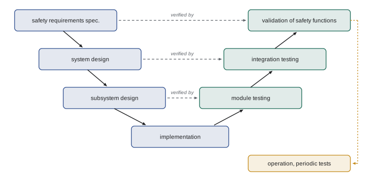
| Validation activity | What it involves for a robot cell |
|---|---|
| Analysis | Review of the specification, circuit diagrams, FMEA, PFH calculations, CCF score and fault exclusions |
| Functional testing | Operate every safety function in every mode and check the response, including reset and restart behavior |
| Fault injection | Disconnect one channel, short a contact, simulate a welded contactor and confirm detection and safe response |
| Response time measurement | Measure stopping time at worst-case speed, payload and extension; compare with the distances used |
| Environmental checks | Confirm ratings for temperature, vibration, ingress protection and electromagnetic compatibility |
| Documentation review | Check that manuals state proof tests, replacement intervals (T10d) and residual risks |
ISO 13849-2 contains annexes listing faults to consider for mechanical, pneumatic, hydraulic and electrical components, and the conditions under which a fault may be excluded, such as a welded contact in a switch with positive opening contacts. Every fault exclusion must be justified and documented, because excluded faults are invisible to the calculation; a long list of unjustified exclusions is a common reason assessors reject designs.
Validation is not a one-time event. Periodic testing confirms that safety functions still work: daily or shift checks of light curtains with a test rod, regular stopping time measurements, and proof tests at intervals stated in component safety manuals. Brake wear, loosened mounts and changed robot programs can all lengthen stopping times. Modifications to safety functions, including software changes in safety PLCs, should go through management of change, with impact analysis and revalidation of affected functions, and versions of safety software should be controlled and checksummed so that unauthorized changes are detectable.
Worked problem
Planning a fault-injection test
A gate interlock uses two switches into a safety relay that drives two contactors with mirror contacts in its feedback loop. Plan three fault-injection tests and the expected result of each.
Show solution
- Disconnect channel 2 of the gate switch while the gate is closed: the relay should detect the discrepancy and prevent reset or restart.
- Short channel 1 to supply while the gate is closed, then open the gate: the relay should still stop via channel 2 and lock out on discrepancy.
- Simulate a welded contactor by holding one contactor's mirror contact open: the relay should refuse to reset after the next stop.
- Record each result, restore wiring and repeat the functional test before returning the cell to service.
Answer: Each test confirms a claimed diagnostic: discrepancy detection on the input, single-fault tolerance on the input and contactor monitoring on the output.
Machine learning in safety functions
Current machinery safety standards assume that safety-related software is specified, designed and tested in ways that make its behavior predictable. Machine-learned perception, such as a neural network that detects people in camera images, does not fit easily: its behavior is defined by training data rather than explicit requirements, its failure modes are hard to enumerate, and its performance can degrade when conditions differ from its training. ISO/IEC TR 5469:2024, Artificial intelligence: Functional safety and AI systems, describes the challenges and suggests approaches, but it is a technical report rather than a requirements standard.
In practice, robot designers keep machine learning outside the certified safety function or wrap it inside a safety-rated envelope. A mobile robot may use learned perception to plan efficient paths among people, while a certified laser scanner with a protective field enforces a stop if anything gets too close, regardless of what the learned system believes. A manipulator may use learned grasping while safety-rated speed, zone and force limits bound its motion. This architecture is sometimes called a safety cage or simplex architecture. Regulators are beginning to address the gap directly. The EU Machinery Regulation, discussed in lesson 5, lists machinery and safety components with fully or partially self-evolving behavior using machine learning to ensure safety functions among the categories that need third-party conformity assessment. Standards committees are drafting requirements for AI in safety functions, so engineers should expect this area to change quickly.
Common mistakes
MistakeTreating a SIL-capable component as making the whole function SIL 3.
InsteadThe SIL of a function depends on all subsystems, their architectures and the conditions in each safety manual.
MistakeIgnoring the common cause factor in redundant subsystems.
InsteadEstimate beta from measures against common causes; it often dominates PFH.
MistakeValidating only by checking that the robot stops when the gate opens.
InsteadInclude analysis, fault injection, response time measurement and environmental checks under a written plan.
MistakeExcluding faults without written justification.
InsteadJustify each exclusion against the criteria in ISO 13849-2 or IEC 62061 and record it.
MistakeUsing a learned person detector as the only means of stopping a robot.
InsteadBound learned components with certified safety functions until standards recognize ML for safety.
Summary and key terms
- IEC 61508 is the basic functional safety standard; it defines SIL 1 to 4 and requires measures against random and systematic failures.
- IEC 62061:2021 applies the SIL approach to machinery of all technologies; SIL 1, 2 and 3 roughly correspond to PL b or c, d and e.
- The required SIL comes from severity and a class value summing frequency, probability and avoidance scores.
- Subsystems must meet PFH targets and architectural constraints based on hardware fault tolerance and safe failure fraction.
- Common cause failures usually dominate the PFH of redundant subsystems.
- Validation under ISO 13849-2 combines analysis, functional testing, fault injection, response time measurement and documentation, and continues through periodic tests and controlled modifications.
- Machine learning is currently kept outside or bounded by certified safety functions, while standards and regulations catch up.
- SIL
- Safety integrity level, a measure of the reliability required of a safety function.
- PFH
- Average frequency of dangerous failure per hour.
- PFDavg
- Average probability of failure on demand, used for low-demand functions.
- Systematic failure
- A failure caused by errors in specification, design, manufacture or software.
- HFT
- Hardware fault tolerance, the number of faults tolerated without loss of function.
- SFF
- Safe failure fraction, the share of failures that are safe or detected.
- Beta factor
- The fraction of failures assumed to affect both channels from a common cause.
- Validation
- Confirming that the finished safety function meets its specification in the real machine.
- Proof test
- A periodic test that reveals undetected dangerous faults.
Practice problems
Work each problem on paper first, then reveal the answer to check.
Which SIL corresponds to PL d?
Show answer
SIL 2.
Se = 4, Fr = 5, Pr = 4, Av = 3: what is Cl?
Show answer
\( 5 + 4 + 3 = 12 \).
A single-channel subsystem has SFF of 92 percent. Maximum SIL by architecture?
Show answer
SIL 2 (HFT 0, SFF 90 to under 99 percent).
Convert an MTTFd of 100 years to a failure rate per hour.
Show answer
\( 1/(100 \times 8760) \approx 1.14 \times 10^{-6} \) per hour.
With beta of 5 percent and lambda of 2e-6 per hour, what is the common cause term?
Show answer
\( 0.05 \times 2 \times 10^{-6} = 1 \times 10^{-7} \) per hour.
Name three validation activities beyond functional testing.
Show answer
Analysis, fault injection, response time measurement, environmental checks, documentation review.
Why must fault exclusions be justified?
Show answer
Excluded faults are invisible to the calculation, so an unjustified exclusion overstates reliability.
Describe a safety cage architecture.
Show answer
A learned planner or perception system operates freely within limits enforced by certified safety functions such as scanner fields and speed limits.
Lesson quiz · 5 questions
Score 60% or more to complete this lesson.
Create a free account to save your progress, take quizzes and earn a certificate.