
CON-240 · Lesson 4 of 12 · 34 min
Beams, columns and frames
Beams and columns are the backbone of most building structures. Beams carry load sideways to their supports through bending; columns carry it down through compression. When beams and columns are joined rigidly they form frames, which can also resist sideways forces. This lesson shows how beams develop shear and bending moment, why deflection matters as much as strength, why columns buckle, and how frames and cantilevers behave. It ends with the practical consequences for construction managers: why you must not notch, core or overload beams, and why temporary column and shore lengths matter.
The formulas here are standard results for simple cases. Real design involves many more checks, done by engineers. Use these results to build intuition and to sanity-check site situations, not to approve structural decisions.
Simply supported beams
A simply supported beam rests on two supports and is free to rotate at each. Under a uniform load w along a span L, each support reaction is half the total load, the shear force is greatest at the supports and falls to zero at mid-span, and the bending moment is zero at the supports and greatest at mid-span.
For a single point load P at mid-span, the reactions are P/2 and the maximum moment is PL/4. These two results, wL²/8 and PL/4, are the most useful formulas in practical structures.
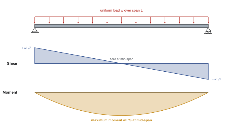
The shape of these diagrams explains where reinforcing and connections are concentrated. In a concrete beam, the bottom bars are heaviest at mid-span where the moment is greatest, and the stirrups are closest together near the supports where the shear is greatest. In a steel beam, holes and copes near supports reduce shear capacity, while flange cuts near mid-span reduce bending capacity.
Worked problem
Moment and shear in a floor beam
A floor beam spans 9.0 m and carries a factored uniform load of 28 kN/m. Find the reactions, maximum shear and maximum moment.
Show solution
- Total load: 28 × 9.0 = 252 kN.
- Reactions and maximum shear: 252 ÷ 2 = 126 kN.
- Maximum moment: wL²/8 = 28 × 9.0² ÷ 8 = 28 × 81 ÷ 8 ≈ 284 kN·m.
Answer: Reactions and shear 126 kN; maximum moment about 284 kN·m.
The span appears squared in the moment formula, so a modest increase in span has a large effect. A beam spanning 10 m carries about 23 per cent more moment than one spanning 9 m under the same uniform load. That is why changing a column location on site, or removing a temporary support early, can overload a beam.
Bending stress and section shape
Bending creates tension on one face and compression on the other, with the largest stresses at the extreme fibres. The bending stress depends on the moment and on a property of the cross-section called the section modulus, S. Deep sections have much larger section moduli than shallow ones of the same area, which is why beams are deep and why steel beams are I-shaped: most of the material is in the flanges, far from the centre, where it does the most work.
Worked problem
Why depth matters
Compare the section modulus of a 38 × 235 mm joist (a 2 × 10) on edge with the same piece laid flat.
Show solution
- On edge: b = 38, h = 235: S = 38 × 235² ÷ 6 ≈ 350,000 mm³.
- Flat: b = 235, h = 38: S = 235 × 38² ÷ 6 ≈ 56,600 mm³.
- On edge it is about 6.2 times stronger in bending, the ratio of depth to width.
Answer: About six times stronger on edge, which is why joists and beams are never laid flat.
This principle explains several site rules. Drilling a hole near the top or bottom edge of a joist removes material where bending stress is highest, so codes and manufacturers limit holes to the middle third of the depth and away from mid-span. Notching the bottom of a beam at a support reduces shear capacity and can start a split. Engineered joists and I-joists have specific hole charts; follow them exactly.
Deflection
A beam can be strong enough and still be unacceptable if it deflects too much. Excessive deflection cracks finishes and partitions, makes floors bouncy, causes ponding on roofs and jams doors and windows. Codes and design standards limit deflection to a fraction of the span, commonly L/360 for floors under live load and L/240 or L/180 for roofs or total load, depending on what the beam supports.
For a simply supported beam under a uniform load, mid-span deflection depends on the fourth power of the span and inversely on stiffness, the product of the modulus of elasticity E and the moment of inertia I.
Worked problem
Checking a deflection limit
A floor beam spans 7.2 m. What is the live load deflection limit at L/360? If the calculated live load deflection is 24 mm, does it pass?
Show solution
- Limit: 7,200 mm ÷ 360 = 20 mm.
- Calculated: 24 mm, which exceeds 20 mm.
- It fails the serviceability check; the engineer would choose a deeper or stiffer section.
Answer: Limit 20 mm; 24 mm fails.
Because deflection rises with the fourth power of span, doubling the span multiplies deflection by sixteen. Concrete members also deflect more over time because of creep and shrinkage, which is one reason engineers specify camber, minimum stripping times and long-term deflection checks. Construction managers see this in practice when a slab edge sags and the curtain wall anchors no longer line up, or when a long-span floor needs to be cambered or shored to final levels.
| Element | Typical deflection limit | Why |
|---|---|---|
| Floor beams under live load | L/360 | Protect finishes and limit vibration |
| Floors supporting brittle partitions or masonry | L/480 or stricter | Prevent cracking |
| Roof members, no plaster ceiling | L/180 to L/240 | Limit ponding and visible sag |
| Members supporting curtain wall or cladding | Specified absolute limit, often small | Protect cladding joints and anchors |
| Formwork surfaces (exposed concrete) | Often L/270 or a set limit | Control finished surface tolerance |
Columns and buckling
A short, stocky column fails by crushing or yielding when the stress reaches the material's strength. A long, slender column fails earlier by buckling: it suddenly bows sideways. The Swiss mathematician Leonhard Euler showed in 1757 that the buckling load of an ideal pin-ended column depends on its stiffness and inversely on the square of its length.
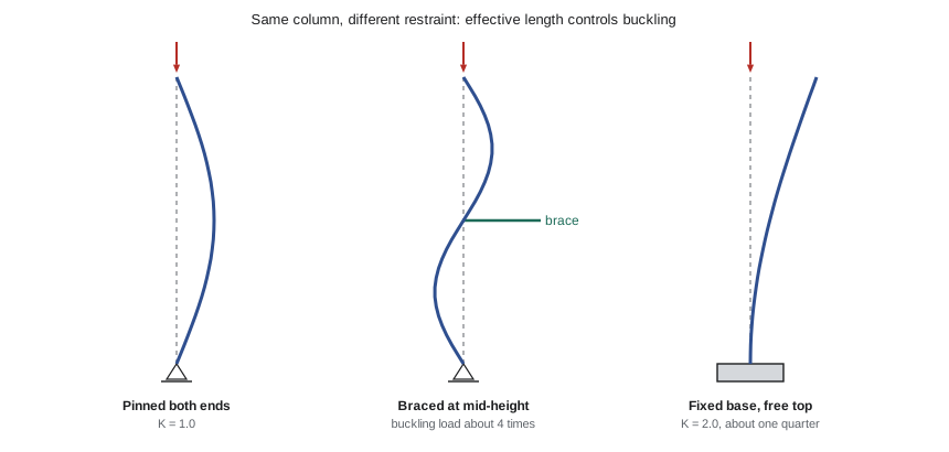
Here K is an effective length factor that depends on how the ends are restrained: about 1.0 for pinned ends, about 0.5 for ends fixed against rotation and 2.0 for a flagpole fixed at the base and free at the top. Because length is squared, doubling the unbraced length of a column cuts its buckling capacity to a quarter. Bracing a column at mid-height halves its effective length and quadruples its buckling capacity.
Worked problem
Effect of bracing on a shore
A steel post shore has an Euler buckling load of 60 kN at an unbraced length of 3.6 m. What is the buckling load if it is braced at mid-height in both directions? What if it is extended to 4.8 m unbraced?
Show solution
- Braced at mid-height: effective length 1.8 m, half the original, so load × 4 = 240 kN (crushing or the shore's rated capacity will govern first).
- Extended to 4.8 m: length ratio 4.8 ÷ 3.6 = 1.33; load ÷ 1.33² = 60 ÷ 1.78 ≈ 34 kN.
- Small changes in shore length or missing bracing have large effects.
Answer: About 240 kN theoretical when braced; about 34 kN at 4.8 m unbraced.
This is why manufacturers publish shore and scaffold capacities that drop with extension length and that assume specified bracing. Using a shore at a longer extension than its table allows, or leaving out its bracing, can cut its capacity dramatically. Many formwork collapses trace back to exactly this.
Cantilevers
A cantilever is fixed at one end and free at the other, like a balcony, a canopy or an overhanging slab edge. A cantilever has its maximum moment at the support, not in the middle, and the top face is in tension. For a uniform load over a cantilever of length L, the support moment is wL²/2, four times that of a simply supported beam of the same length.
For construction, cantilevers have two important implications. First, their top reinforcing is critical: if top bars are stepped on and pushed down before concrete placement, the cantilever loses much of its strength. Second, cantilevers depend on the back span or the connection to stay in place; removing shores under a cantilever before the back span has gained strength, or before post-tensioning, can lead to failure.
Worked problem
A cantilevered balcony
A concrete balcony cantilevers 1.8 m and carries a factored uniform load of 12 kN/m per metre of width. What is the support moment per metre of width?
Show solution
- M = wL²/2 = 12 × 1.8² ÷ 2 = 12 × 3.24 ÷ 2 ≈ 19.4 kN·m per metre.
- That moment is resisted by top bars, so their height in the slab is critical.
Answer: About 19.4 kN·m per metre width.
Continuous beams and frames
Most real beams are not simply supported. Concrete beams and slabs are usually continuous over several supports, and steel beams in moment frames are rigidly connected to columns. Continuity reduces mid-span moments and deflections but creates negative moments over the supports, where the top face goes into tension. That is why concrete slabs have top bars over columns and beams, and why stripping or reshoring sequences must respect how the engineer assumed the structure would behave.
A frame is a structure of beams and columns joined so that the joints transfer moment. Moment frames resist lateral loads through the bending of their members. Braced frames resist lateral loads through diagonal braces working in tension and compression. Shear walls resist lateral loads through their in-plane strength. Each lateral system has construction implications covered in later lessons: moment frame connections need careful welding and inspection, braced frames need their braces installed before the frame is loaded laterally, and shear walls need continuous reinforcing and proper construction joints.
| Lateral system | How it works | Construction notes |
|---|---|---|
| Moment frame | Rigid beam-column joints resist sway through bending | Connection welding and inspection critical; frames are flexible until complete |
| Braced frame | Diagonal braces carry lateral loads axially | Install braces in sequence; temporary bracing until permanent braces are in |
| Shear wall | Walls resist lateral loads in their own plane | Continuous reinforcing, hold-downs and construction joints matter |
| Core (concrete) | Stair and elevator walls form a stiff tube | Often built ahead of the floors with jump or slip forms |
What this means on site
The behaviour of beams, columns and frames leads directly to site rules that a construction manager should enforce.
- Do not cut, notch, core or drill structural members without the engineer's written approval, and follow manufacturers' hole charts for engineered wood.
- Keep top reinforcing at its specified height, especially in cantilevers and over supports; use chairs and do not walk on bar mats unsupported.
- Do not change spans by moving or removing supports, shores or posts without engineering review.
- Use shores and scaffold frames within their rated extension and with the specified bracing.
- Watch for unexpected deflection, cracking or sagging during construction and stop work to investigate.
- Install permanent bracing and connections in the sequence the erection plan requires.
Common mistakes
MistakeAssuming a slightly longer span makes little difference.
InsteadMoment grows with the square of the span and deflection with the fourth power; small changes matter.
MistakeDrilling holes near the top or bottom of a joist.
InsteadHoles belong near mid-depth and in the zones the engineer or manufacturer allows; edges carry the highest bending stresses.
MistakeExtending a shore beyond its rated length or omitting its bracing.
InsteadBuckling capacity falls with the square of unbraced length; use the manufacturer's tables and bracing.
MistakeLetting workers flatten top bars in a cantilever.
InsteadTop bars resist the cantilever's support moment; keep them at the specified height with proper supports.
MistakeJudging a beam only by strength.
InsteadDeflection limits often govern; excessive deflection damages finishes and cladding.
Summary and key terms
- A simply supported beam under uniform load has reactions wL/2 and maximum moment wL²/8 at mid-span.
- Shear peaks at supports and bending moment peaks at mid-span, which drives where reinforcing and holes can go.
- Bending stress is M/S, and deep sections such as I-beams are efficient in bending.
- Deflection grows with the fourth power of span and is limited to fractions such as L/360.
- Slender columns buckle; capacity falls with the square of the effective length.
- Cantilevers have maximum moment at the support and depend on top reinforcing and back spans.
- Continuous beams and frames have negative moments over supports, and lateral systems include moment frames, braced frames and shear walls.
- Simply supported beam
- A beam resting on two supports that do not resist rotation.
- Shear force diagram
- A graph of internal shear along a member.
- Bending moment diagram
- A graph of internal bending moment along a member.
- Section modulus (S)
- A cross-section property relating bending moment to extreme fibre stress.
- Moment of inertia (I)
- A cross-section property measuring stiffness in bending.
- Deflection
- The vertical movement of a member under load.
- Buckling
- Sudden sideways failure of a slender compression member.
- Effective length
- The length of an equivalent pin-ended column, accounting for end restraint.
- Cantilever
- A member fixed at one end and free at the other.
- Negative moment
- Bending that puts the top face in tension, as over continuous supports.
Practice problems
Work each problem on paper first, then reveal the answer to check.
A beam spans 6 m with w = 20 kN/m. What is the maximum moment?
Show answer
20 × 36 ÷ 8 = 90 kN·m.
A 40 kN point load acts at mid-span of an 8 m beam. What is the maximum moment?
Show answer
PL/4 = 40 × 8 ÷ 4 = 80 kN·m.
By what factor does moment change if span increases by 20 per cent?
Show answer
1.2² = 1.44, so about 44 per cent more.
By what factor does deflection change if span doubles under the same load per length?
Show answer
2⁴ = 16 times.
What is the L/360 limit for a 9 m beam?
Show answer
25 mm.
A shore's unbraced length is reduced by half. How does its buckling load change?
Show answer
It increases about four times, though the rated capacity may limit it.
A 2 m cantilever carries w = 8 kN/m. What is the support moment?
Show answer
8 × 4 ÷ 2 = 16 kN·m.
Where is the tension face in a cantilever?
Show answer
The top face.
Why do continuous concrete slabs need top bars over supports?
Show answer
Negative moment over supports puts the top face in tension.
Name three lateral force resisting systems.
Show answer
Moment frames, braced frames and shear walls (or cores).
Lesson quiz · 5 questions
Score 60% or more to complete this lesson.
Create a free account to save your progress, take quizzes and earn a certificate.