
CON-260 · Lesson 2 of 12 · 28 min
BIM concepts, dimensions and levels of development
Building information modelling is often described as 3D design, but the geometry is only part of it. A BIM model is a database of objects: walls, doors, beams, ducts, pumps, rooms and zones, each with a type, properties and relationships to other objects. Drawings, schedules and quantities are views of that database. If a door type changes in the model, every plan, elevation and door schedule that shows it changes too. CON-120 introduced this idea and the basic file formats. This lesson builds the vocabulary a construction manager needs to specify, judge and use models: objects and properties, the so-called dimensions of BIM, levels of development, and level of information need.
Objects, types and properties
In a BIM authoring tool, every element belongs to a category (such as wall, door or duct), a family or type (for example, a 200 mm concrete block wall, or a single-flush steel door 915 × 2134 mm) and an instance (one particular wall or door at one location). Properties can belong to the type, so they are shared by every instance (fire rating, manufacturer, assembly code), or to the instance (room number, mark, phase). Good modelling practice puts each property in the right place so that changing a type changes every instance consistently.
Objects also carry relationships. A door is hosted by a wall, a wall is bounded by a level, a room is defined by its bounding walls, and a pump is connected to a pipe system. These relationships are what let the software update dependent elements automatically and calculate quantities, areas and system flows. They are also why a model made of dumb 3D shapes, such as a mesh exported from a visualization tool, is not BIM even if it looks identical.
| Level | Example | Typical properties |
|---|---|---|
| Category | Doors | Common behaviour: hosted in walls, appear in door schedules |
| Type | Single-flush hollow metal door, 90-minute rating | Fire rating, frame type, hardware set, manufacturer, cost code |
| Instance | Door 2-114 on level 2 | Mark, room from/to, phase, installation status |
Classification systems give objects consistent codes so data can be sorted, costed and compared across projects. In North America the most common are MasterFormat (work results, used for specifications and many cost reports), UniFormat (building elements, useful for early estimates) and OmniClass (a broader set of tables that includes products, spaces and phases). A model in which every element carries a UniFormat or MasterFormat code can produce an elemental estimate or a trade-by-trade quantity report with little manual sorting.
The dimensions of BIM
Industry marketing often describes BIM in dimensions. The first three are geometry: x, y and z. Beyond that, the numbers are labels for uses, not mathematical dimensions, and different sources number them differently. The most widely used meanings are shown below. Treat them as shorthand, and always define what you mean in a contract.
| Label | Common meaning | Typical use |
|---|---|---|
| 3D | Geometry and properties | Design, visualization, coordination, clash detection |
| 4D | 3D linked to time (schedule) | Sequencing, logistics, phasing, progress visualization |
| 5D | 3D linked to cost | Quantity takeoff, estimates, cash flow, change pricing |
| 6D | Varies: often sustainability or operations | Energy and carbon analysis, or facility management data |
| 7D | Varies: often facility management | Asset data for operation and maintenance |
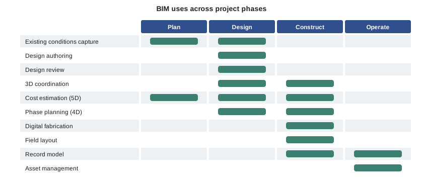
A more precise approach, used by the National BIM Standard–United States and many owners, is to describe BIM uses: specific purposes such as design authoring, design review, 3D coordination, cost estimation, phase planning, site utilization planning, digital fabrication, field layout, record modelling and asset management. Each use implies certain model content, people and software. Lesson 4 shows how a BIM execution plan selects uses and assigns responsibility for each.
Level of development (LOD)
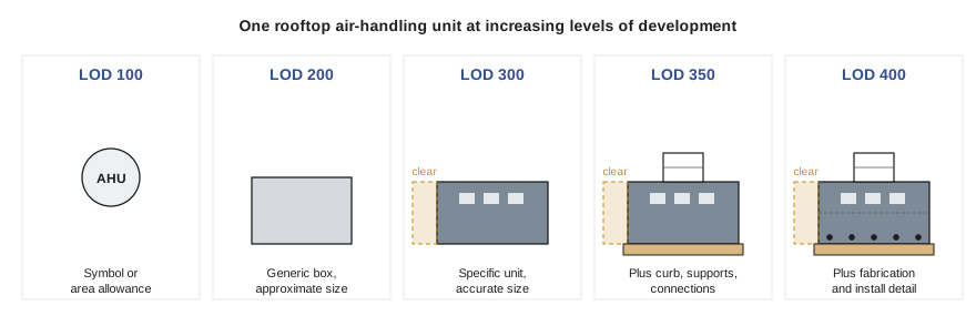
A model element can be anything from a placeholder box to a fabrication-ready assembly. Without a shared way of describing how far an element has been developed, a contractor cannot tell whether a duct in the design model can be used for coordination or is merely an indication of intent. Level of development (LOD) answers that question. The North American reference is the LOD Specification published by BIMForum; its 2025 edition was released at the end of 2025.
LOD describes how much the geometry and information of an element can be relied on, not how detailed the graphics look. A beautifully rendered chair can be LOD 100 if its size and position are only indicative, and a plain grey box can be LOD 300 if it accurately represents the space reserved for a piece of equipment.
| LOD | Element represents | Reliability for a contractor |
|---|---|---|
| 100 | A symbol or generic representation; may show that an element exists | Cost per area, conceptual massing only |
| 200 | A generic system, object or assembly with approximate quantities, size, shape, location and orientation | Approximate; not for coordination |
| 300 | A specific system, object or assembly with measurable quantity, size, shape, location and orientation | Suitable for coordination and quantity takeoff at design stage |
| 350 | As 300, plus interfaces with other building systems (supports, connections, clearances) | Suitable for detailed trade coordination |
| 400 | As 350, with detailing, fabrication, assembly and installation information | Suitable for fabrication and installation |
| 500 | Field-verified representation (not a progression level in the BIMForum specification) | Record of what was built, verified on site |
Several points often cause confusion. LOD is assigned to elements, not to whole models: a model at the end of design development might have walls at LOD 300, ducts at LOD 200 and furniture at LOD 100. LOD 350 was added because trade coordination needs supports, hangers, clearances and connections that LOD 300 does not require. And LOD 500 is about verification against the built work, not a further step in detail; BIMForum does not define it as a progression level.
Some practitioners distinguish level of detail (the amount of graphic detail) from level of development (how much can be relied on), and level of accuracy for survey and scan data, specified separately by the U.S. Institute of Building Documentation. In contracts, always say which you mean and refer to a named specification and edition.
Model element tables
The practical tool for LOD is a model element table (sometimes called a model progression specification or LOD matrix). Rows list element types, often organized by UniFormat; columns list project milestones; each cell gives the LOD required and the party responsible for modelling the element (the model element author). The table becomes part of the BIM execution plan and, on many projects, part of the contract.
Worked problem
Reading a model element table
A model element table for a mid-rise office building lists, for "D3040 HVAC distribution: ductwork": schematic design LOD 100 (mechanical engineer); design development LOD 200 (mechanical engineer); construction documents LOD 300 (mechanical engineer); coordination LOD 350 (mechanical subcontractor); fabrication LOD 400 (mechanical subcontractor); record LOD 300 field-verified (mechanical subcontractor). The general contractor wants to start clash detection on ductwork using the construction-document model. What can it rely on, and what should it expect to change?
Show solution
- At construction documents, ductwork is LOD 300: sizes, routes and elevations are specific and measurable.
- Hangers, supports, insulation thickness, access clearances and connections are not required until LOD 350.
- So clash detection on the CD model can find major conflicts between mains and structure, but clearances and support conflicts will appear only when the subcontractor models to LOD 350.
- Responsibility for the LOD 350 and 400 model passes to the mechanical subcontractor, so its schedule and contract must include modelling.
Answer: The contractor can use the LOD 300 model for early coordination of main routes, but must plan a second, detailed round with the subcontractor's LOD 350 model before fabrication.
Level of information need
LOD has a weakness: it bundles geometry and information into a single number, which tempts people to over-specify. A client who asks for everything at LOD 400 may pay for detail it never uses. The ISO approach, set out in ISO 7817-1:2024 (which builds on the earlier European standard EN 17412-1), is level of information need. Instead of a single number, each information requirement is defined by purpose and by three components: geometrical information (detail, dimensionality, location, appearance and parametric behaviour), alphanumerical information (identification and the properties needed) and documentation (drawings, certificates, manuals and other documents).
Level of information need starts from the question "What decision or task will this information support?" and specifies only what is needed for that purpose at that milestone. For example, to support a fire strategy review at design stage, a fire door needs its location, rating and direction of swing but not its hardware supplier; for handover, it needs its rating, manufacturer, model, installation date, inspection certificate and maintenance requirements, but the geometry can stay simple.
| Aspect | LOD (BIMForum) | Level of information need (ISO 7817-1) |
|---|---|---|
| Basis | Numbered levels 100–400 plus 500 | Purpose-based description per requirement |
| Geometry and data | Combined in one level | Defined separately: geometry, alphanumeric data, documentation |
| Typical use | North American model element tables | ISO 19650 projects; European and international clients |
| Risk | Over-specification by asking for high LOD everywhere | More work to define requirements carefully |
The two approaches are not exclusive. Many Canadian and American projects use BIMForum LOD for geometry and a separate property list (for example, COBie fields or the owner's asset attributes) for information, which moves toward the ISO idea in practice.
Model quality: what makes a model trustworthy
A model is only useful if it is reliable. Model quality checks fall into three groups. Visual checks look for obvious errors such as missing elements or elements on the wrong level. Rule-based checks use software to test properties and geometry against rules: every door has a fire rating, no wall is shorter than 2.1 m, every room has a number, every element has a classification code. Coordination checks find clashes between disciplines (Lesson 5).
Worked problem
Checking property completeness
A model checker reports that a design-development model contains 1,240 doors. Of these, 1,178 have a fire-rating value, 1,093 have a hardware set, and 1,240 have a mark. The BIM execution plan requires 98 % completeness for fire rating and 90 % for hardware set at this milestone. Does the model pass?
Show solution
- Fire rating completeness = 1,178 ÷ 1,240 ≈ 95.0 %, below the 98 % required.
- Hardware set completeness = 1,093 ÷ 1,240 ≈ 88.1 %, below the 90 % required.
- Mark completeness = 100 %.
- The model fails on two properties; the architect should fill missing values (62 fire ratings and 147 hardware sets) before the milestone is accepted.
Answer: The model does not yet meet the agreed information requirements. Rule-based checks make the gaps objective rather than a matter of opinion.
A model also needs a defined coordinate system, consistent levels and grid, agreed units and a shared origin. Mismatched origins are a classic problem: the architectural model sits at one point and the structural model 300 m away, or rotated to true north while the other uses project north. The BIM execution plan should fix the project base point and survey point, tied to the site control described in CON-250.
Who owns and authors each element
Every element has an author responsible for its geometry and data at each stage. When responsibility moves (for example, from the design engineer to the trade detailer at LOD 350), the handover must be explicit so that the design model and the trade model do not both claim to be authoritative. Many disputes arise from ambiguity here: a design engineer assumes the contractor will finalize sizes, the contractor assumes the design model is correct, and nobody checks the gap.
Authoring responsibility is distinct from intellectual property and from contractual reliance, which Lesson 11 covers. The construction manager's practical job is to make sure the model element table names an author for every element at every milestone, and that the schedule allows time for each transfer.
Common mistakes
MistakeTreating a model that looks detailed as reliable.
InsteadJudge reliability by the stated LOD or information requirement, not by the graphics.
MistakeSpecifying LOD 400 for every element at every stage.
InsteadSet the LOD or level of information need by purpose and milestone; over-specification wastes money.
MistakeAssigning one LOD to a whole model.
InsteadAssign LOD element by element in a model element table.
MistakeAssuming LOD 500 means more detail than LOD 400.
InsteadLOD 500 refers to field verification of what was built, not a further level of detail.
MistakeLeaving coordinate origins to each modeller.
InsteadFix the project base point, survey point and orientation in the BIM execution plan and tie them to site control.
Summary and key terms
- A BIM model is a database of objects with types, properties and relationships; drawings and schedules are views of it.
- Classification systems such as UniFormat, MasterFormat and OmniClass let model data be sorted and costed.
- 4D links models to time and 5D to cost; higher dimension labels are used inconsistently, so BIM uses are more precise.
- LOD describes how much an element's geometry and information can be relied on, from 100 to 400, with LOD 500 meaning field-verified.
- LOD is assigned element by element in a model element table that also names the author.
- ISO 7817-1 level of information need defines geometry, alphanumeric data and documentation by purpose.
- Model quality depends on visual, rule-based and coordination checks and on shared coordinates.
- Each element needs a named author at each milestone, with explicit transfers between parties.
- Building information modelling (BIM)
- Creating and managing structured digital information about a built asset, including object-based models.
- Type property
- A property shared by all instances of a type.
- Instance property
- A property specific to one occurrence of an element.
- UniFormat
- A classification of building elements used for early estimates and model organization.
- BIM use
- A defined purpose for which a model is created or used, such as 3D coordination.
- Level of development (LOD)
- The degree to which an element's geometry and information can be relied on.
- Model element table
- A matrix of element types and milestones giving required LOD and author.
- Level of information need
- An ISO 7817-1 framework defining required geometry, data and documentation by purpose.
- Model element author
- The party responsible for an element's content at a milestone.
- Project base point
- The model reference point tied to the project grid and site control.
Practice problems
Work each problem on paper first, then reveal the answer to check.
What is the difference between a type property and an instance property?
Show answer
A type property is shared by all instances of that type; an instance property belongs to one element.
Which classification system is organized by building elements and suits early estimates?
Show answer
UniFormat.
What does 4D BIM link to the model?
Show answer
Time, through the schedule.
At which LOD do supports, hangers and interfaces with other systems appear?
Show answer
LOD 350.
A rendered sofa has only indicative size and location. What LOD might it be?
Show answer
LOD 100 or 200; graphics do not determine LOD.
What are the three components of level of information need?
Show answer
Geometrical information, alphanumerical information and documentation.
A model has 820 of 860 pumps with a manufacturer property. The requirement is 95 %. Does it pass?
Show answer
820 ÷ 860 ≈ 95.3 %; it passes.
Why is LOD 500 not a progression level?
Show answer
It describes field verification of built work, not more detail.
Give two examples of rule-based model checks.
Show answer
Every door has a fire rating; every room has a number; every element has a classification code.
Why must the project base point be fixed in the execution plan?
Show answer
So all discipline models share the same origin and orientation and align when federated.
Lesson quiz · 5 questions
Score 60% or more to complete this lesson.
Create a free account to save your progress, take quizzes and earn a certificate.