
ELE-202 · Lesson 10 of 12 · 36 min
Capacitors and inductors: energy storage in circuits
Lesson 1 introduced capacitors and inductors through their defining equations and their DC behaviour as open and short circuits. This lesson develops them further, because almost every real circuit stores energy somewhere: in the filter capacitors of a power supply, the inductor of a buck converter, the hold-up capacitors that keep a server running through a brief power dip, or the parasitic capacitance of a long cable. We find voltages and currents from changing waveforms, combine capacitors and inductors in series and parallel, solve circuits in DC steady state, determine initial conditions at the moment a switch operates, and build op amp integrators. These are the foundations on which ELE-203 builds transient and AC analysis.
From current to voltage, and back
The capacitor equation \(i = C\,dv/dt\) can be integrated to give the voltage from the current:
The capacitor remembers its past: its present voltage depends on all the current that has ever flowed into it, summarized by the initial voltage \(v(t_{0})\). The dual statements hold for an inductor:
Graphically, the change in capacitor voltage over an interval is the area under the current curve divided by \(C\). For piecewise-constant currents, each segment gives a straight-line ramp in voltage.
Worked problem
Voltage from a current waveform
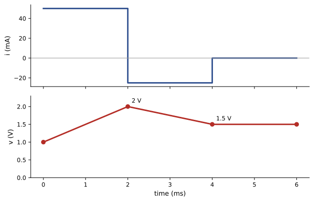
A 100 µF capacitor starts at 1 V. It is charged with 50 mA for 2 ms, then discharged with 25 mA for 2 ms, then left alone. Find its voltage at 2 ms, 4 ms and 6 ms, and the stored energy at the end.
Show solution
- 0 to 2 ms: \(\Delta v = 0.05 \times 0.002/(100 \times 10^{-6}) = 1.0\) V, so \(v = 2.0\) V.
- 2 to 4 ms: \(\Delta v = -0.025 \times 0.002/(100 \times 10^{-6}) = -0.5\) V, so \(v = 1.5\) V.
- After 4 ms, \(i = 0\), so the voltage stays at 1.5 V.
- Energy: \(w = \tfrac{1}{2} \times 100 \times 10^{-6} \times 1.5^{2} = 0.1125\) mJ.
Answer: 2.0 V, 1.5 V and 1.5 V, with 0.1125 mJ stored at the end. The capacitor holds its charge indefinitely if ideal; a real one slowly loses it through leakage.
import numpy as np

C = 100e-6                         # 100 uF
dt = 1e-5
t = np.arange(0, 0.006 + dt / 2, dt)
i = np.where(t < 0.002, 0.05, np.where(t < 0.004, -0.025, 0.0))   # 50 mA, then -25 mA, then 0

v = 1.0 + np.concatenate([[0.0], np.cumsum(i[:-1] * dt)]) / C   # v(0) = 1 V; v = v0 + (1/C) * integral of i
w = 0.5 * C * v**2
for tk in [0, 0.002, 0.004, 0.006]:
    k = int(round(tk / dt))
print(f"t = {tk * 1e3:.0f} ms: v = {v[k]:.3f} V, stored energy = {w[k] * 1e3:.3f} mJ")t = 0 ms: v = 1.000 V, stored energy = 0.050 mJ t = 2 ms: v = 2.000 V, stored energy = 0.200 mJ t = 4 ms: v = 1.500 V, stored energy = 0.112 mJ t = 6 ms: v = 1.500 V, stored energy = 0.112 mJ
Numerical integration like this is how simulators handle capacitors and inductors in transient analysis: they replace the derivative with a small time step and solve a resistive circuit at each step (ELE-203).
Series and parallel combinations
Capacitors combine like conductances, and inductors like resistances:
Capacitors in series share the same charge, so the voltage divides in inverse proportion to capacitance: the smaller capacitor takes the larger voltage. This matters when capacitors are stacked to reach a higher voltage rating, as in supercapacitor modules and the DC bus of power converters: unequal capacitance or leakage would overstress one of them, so balancing resistors or active balancing circuits are added.
Worked problem
Capacitors in series
A 10 µF and a 40 µF capacitor are connected in series across 100 V DC and allowed to charge fully from zero. Find the equivalent capacitance, the charge, and the voltage on each.
Show solution
- \(C_{ser} = (10 \times 40)/(10 + 40) = 8\) µF.
- Charge: \(Q = 8 \times 10^{-6} \times 100 = 800\) µC, the same on both.
- Voltages: \(V_{10} = 800/10 = 80\) V; \(V_{40} = 800/40 = 20\) V.
Answer: 8 µF, 800 µC, and 80 V across the 10 µF capacitor but only 20 V across the 40 µF one. If both were rated 63 V, the smaller would be overstressed even though the total is well below their combined rating.
DC steady state
When a circuit containing capacitors and inductors has been connected to DC sources for a long time, all voltages and currents stop changing. Then every capacitor carries no current (an open circuit) and every inductor has no voltage (a short circuit). DC steady-state analysis replaces them accordingly and solves the remaining resistive circuit with the methods of Lessons 2 to 6. The capacitor voltages and inductor currents found this way give the stored energy.
Worked problem
Energy stored in steady state
A 24 V source feeds a 4 Ω resistor in series with a parallel combination of a 2 mH inductor and a 12 Ω resistor. A 470 µF capacitor is connected across the 12 Ω resistor. Find the inductor current, the capacitor voltage and the total stored energy in DC steady state.
Show solution
- Replace the inductor by a short and the capacitor by an open circuit. The short is in parallel with the 12 Ω resistor and the capacitor, so the voltage across all three is zero.
- Current: \(24/4 = 6\) A, all of it through the inductor (none through the shorted 12 Ω).
- Capacitor voltage: 0 V.
- Energy: \(w_{L} = \tfrac{1}{2} \times 0.002 \times 6^{2} = 36\) mJ; \(w_{C} = 0\).
Answer: Inductor current 6 A, capacitor voltage 0 V, total stored energy 36 mJ. Elements in parallel with an inductor see no DC voltage, and elements in series with a capacitor carry no DC current: noticing these cases first saves work.
Switching and initial conditions
Circuits change suddenly when switches open or close, breakers trip or transistors turn on. The key facts for analysing the instant of switching, at \(t = 0\), come from the defining equations:
- Capacitor voltage cannot change instantaneously: \(v_{C}(0^{+}) = v_{C}(0^{-})\).
- Inductor current cannot change instantaneously: \(i_{L}(0^{+}) = i_{L}(0^{-})\).
- Everything else, capacitor current, inductor voltage, resistor voltages and currents, can jump.
The procedure is: (1) find the DC steady state before switching, giving \(v_{C}(0^{-})\) and \(i_{L}(0^{-})\); (2) at \(t = 0^{+}\), replace each capacitor by a voltage source of value \(v_{C}(0^{-})\) and each inductor by a current source of value \(i_{L}(0^{-})\); (3) solve that resistive circuit for any quantity at \(0^{+}\); (4) find the new final steady state as \(t \to \infty\). ELE-203 then shows how the circuit moves from \(0^{+}\) to its final state, exponentially with time constant \(RC\) or \(L/R\).
Worked problem
Initial and final values
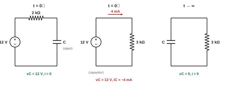
A 12 V source has charged a 10 µF capacitor through 2 kΩ for a long time. At \(t = 0\) a switch disconnects the source and connects the capacitor across a 3 kΩ resistor instead. Find \(v_{C}\), the resistor current and the capacitor current at \(0^{-}\), \(0^{+}\) and \(\infty\).
Show solution
- \(0^{-}\): steady state, no current, \(v_{C} = 12\) V; capacitor current 0.
- \(0^{+}\): \(v_{C}\) is still 12 V; the 3 kΩ resistor current is \(12/3000 = 4\) mA; the capacitor current is −4 mA (discharging).
- \(\infty\): all energy dissipated, \(v_{C} = 0\), all currents 0.
Answer: The capacitor voltage is continuous (12 V just before and just after switching), while its current jumps from 0 to −4 mA. In ELE-203 you will find that it decays as \(12e^{-t/\tau}\) V with \(\tau = RC = 30\) ms.
Op amp integrators and differentiators
Placing a capacitor in the feedback path of an inverting op amp (Lesson 8) gives an integrator. The input current \(v_{i}/R\) flows into the capacitor, so
A constant input produces a linear ramp at the output, at a rate of \(-v_{i}/RC\) volts per second, until the op amp reaches its supply limit. Integrators form the core of analog control loops (the I in PID control, ELE-390), waveform generators and dual-slope ADCs. Swapping the resistor and capacitor gives a differentiator, \(v_{o} = -RC\,dv_{i}/dt\), which is rarely used as drawn because it amplifies high-frequency noise.
Worked problem
An integrator ramp
An integrator has \(R = 100\) kΩ, \(C = 1\) µF and op amp supplies of ±12 V. Its output starts at 0 V. A constant −0.5 V is applied to the input. How fast does the output rise, and when does it reach the supply limit?
Show solution
- \(RC = 100{,}000 \times 10^{-6} = 0.1\) s.
- Rate: \(-(-0.5)/0.1 = +5\) V/s.
- Time to reach about +12 V: \(12/5 = 2.4\) s.
Answer: The output ramps up at 5 V/s and saturates after about 2.4 s. In practice a large resistor is placed across the capacitor, or a reset switch is added, so that the op amp's offset voltage (Lesson 9) does not slowly integrate the output into saturation.
Real capacitors and inductors
Practical components depart from the ideal in ways that often decide a design:
- Capacitors have equivalent series resistance (ESR), which heats them under ripple current, and equivalent series inductance (ESL), which limits their usefulness at high frequency. Their capacitance varies with voltage (strongly for high-k ceramic dielectrics), temperature and age.
- Aluminium electrolytic capacitors offer large capacitance at low cost but have limited life: their electrolyte slowly dries out, and as a rule of thumb life doubles for every 10 °C reduction in operating temperature. They are a leading cause of failure in power supplies and fans.
- Supercapacitors (electric double-layer capacitors) store hundreds to thousands of farads at 2.7 V per cell, bridging the gap between capacitors and batteries.
- Inductors have winding resistance and core losses, and their inductance falls when the core saturates (ELEC-110, Lesson 9).
Worked problem
Hold-up capacitance in a server power supply
A 1,000 W server power supply must keep running for 10 ms after its input fails, drawing energy from capacitors on its 400 V internal DC bus. Its converter keeps working until the bus falls to 300 V. What capacitance is needed?
Show solution
- Energy needed: \(1{,}000 \times 0.010 = 10\) J.
- Energy released as the bus falls: \(\tfrac{1}{2}C(400^{2} - 300^{2}) = \tfrac{1}{2}C \times 70{,}000\).
- \(C = 2 \times 10/70{,}000 = 286\) µF.
Answer: About 286 µF; a designer would choose about 330 µF or more to allow for tolerance, ageing and temperature. This hold-up time lets servers ride through the brief interruption while an automatic transfer switch or UPS changes source (DCE-200), and is specified in industry standards for server power supplies.
Worked problem
Electrolytic capacitor life
An electrolytic capacitor is rated for 5,000 hours at 105 °C. Estimate its life at 65 °C using the 10 °C doubling rule.
Show solution
- Temperature reduction: \(105 - 65 = 40\) °C, four steps of 10 °C.
- Life: \(5{,}000 \times 2^{4} = 80{,}000\) hours, about 9 years.
Answer: About 80,000 hours, or roughly nine years of continuous operation. Running hot shortens it rapidly: at 85 °C the same estimate gives 20,000 hours, about 2.3 years. Cooling and airflow inside equipment therefore directly affect its reliability.
Common mistakes
MistakeForgetting the initial voltage when integrating capacitor current.
InsteadInclude v(t₀): the capacitor remembers its history.
MistakeCombining capacitors in series like resistors.
InsteadCapacitors in series combine like resistors in parallel.
MistakeAssuming capacitors in series share voltage equally.
InsteadVoltage divides inversely with capacitance; add balancing for stacks.
MistakeAssuming capacitor current or inductor voltage is continuous at switching.
InsteadOnly capacitor voltage and inductor current are continuous.
MistakeBuilding an integrator without a reset or DC feedback path.
InsteadAdd a large parallel resistor or a reset switch so offset does not saturate it.
Summary and key terms
- Capacitor voltage is the running integral of current divided by C, plus its initial value; inductor current is the dual.
- Capacitors add in parallel and combine reciprocally in series; inductors combine like resistors.
- In DC steady state, capacitors are open circuits and inductors short circuits.
- At switching, capacitor voltage and inductor current are continuous; other quantities can jump.
- An op amp with a feedback capacitor integrates its input: vo = −(1/RC)∫vi dt.
- Real components have ESR, ESL, saturation, voltage and temperature effects and finite life.
- Hold-up capacitance follows from the energy needed and the allowed voltage drop.
- Initial condition
- The value of a capacitor voltage or inductor current at the start of an interval.
- DC steady state
- The condition after all changes have died out under DC sources.
- 0⁻ and 0⁺
- The instants just before and just after switching.
- Continuity
- The property that capacitor voltage and inductor current cannot jump.
- Integrator
- An op amp circuit whose output is proportional to the integral of its input.
- ESR
- Equivalent series resistance of a capacitor.
- ESL
- Equivalent series inductance of a capacitor.
- Electrolytic capacitor
- A high-capacitance capacitor using a liquid or polymer electrolyte.
- Supercapacitor
- An electric double-layer capacitor with very high capacitance at low voltage.
- Hold-up time
- How long a power supply keeps its output after input power fails.
Practice problems
Work each problem on paper first, then reveal the answer to check.
A 22 µF capacitor carries 11 mA for 4 ms from 0 V. Final voltage?
Show answer
2 V.
A 5 mH inductor has 10 V across it for 2 ms from 0 A. Final current?
Show answer
4 A.
6 µF and 3 µF in series?
Show answer
2 µF.
6 mH and 3 mH in parallel?
Show answer
2 mH.
2 µF and 8 µF in series across 50 V. Voltage on the 2 µF?
Show answer
40 V.
In DC steady state, what current flows through a capacitor?
Show answer
None.
iL(0⁻) = 2 A. What is iL(0⁺)?
Show answer
2 A.
Integrator R = 10 kΩ, C = 0.1 µF, input +1 V. Output slope?
Show answer
−1,000 V/s.
Hold-up: 500 W for 20 ms, bus from 380 V to 300 V. Capacitance?
Show answer
2 × 10/(144,400 − 90,000) ≈ 368 µF.
Rated 2,000 h at 105 °C. Life at 75 °C?
Show answer
16,000 h.
Lesson quiz · 5 questions
Score 60% or more to complete this lesson.
Create a free account to save your progress, take quizzes and earn a certificate.