
ELE-202 · Lesson 6 of 12 · 36 min
Circuit theorems
Nodal and mesh analysis can solve any linear circuit, but they treat every circuit as a fresh system of equations. Often an engineer needs something more insightful: how will the output change if the load changes? What does this complicated network look like from the two terminals where something will be connected? Which source is responsible for which part of the response? The circuit theorems answer these questions. They follow from one property, linearity, and they let engineers replace complicated networks with simple equivalents.
This chapter covers linearity and proportionality, superposition, source transformation, Thévenin's and Norton's theorems, and maximum power transfer. These ideas run through all of electrical engineering. A power system engineer models the entire grid behind a substation as a Thévenin source to calculate fault currents; an electronics designer models an amplifier's output as a Thévenin source to see how a load will pull it down; and a sensor designer uses them to understand how much signal reaches a measuring circuit.
Linearity
A circuit is linear if it contains only linear elements (resistors, capacitors, inductors and linear dependent sources) and independent sources. In a linear circuit, every voltage and current is a linear function of the independent sources. Two properties follow:
- Homogeneity (proportionality): if every independent source is multiplied by a constant \(k\), every response is multiplied by \(k\).
- Additivity: the response to several sources acting together is the sum of the responses to each one acting alone.
Power is not linear: \(p = i^2R\), so doubling the current quadruples the power. Linearity applies to voltages and currents; powers must be computed from the total voltages and currents, never added source by source.
Worked problem
The unit-output method
A ladder network has a 22 V source, a 1 Ω series resistor to node A, 2 Ω from A to the reference, a 1 Ω series resistor from A to node B, and 2 Ω from B to the reference (the output). Find the output voltage.
Show solution
- Assume \(v_B = 1\) V and work backwards. Current in the output 2 Ω: 0.5 A, which also flows in the second 1 Ω.
- \(v_A = 1 + 1 \times 0.5 = 1.5\) V. Current in the 2 Ω at A: 0.75 A.
- Source current: \(0.5 + 0.75 = 1.25\) A. Source voltage needed: \(v_s = 1.5 + 1 \times 1.25 = 2.75\) V.
- So 2.75 V of source gives 1 V of output. By proportionality, 22 V gives \(22/2.75 = 8\) V.
Answer: 8 V. Assuming an output and working backwards avoids simultaneous equations entirely; linearity scales the result.
Superposition
Additivity gives the superposition theorem: in a linear circuit with several independent sources, any voltage or current is the algebraic sum of the contributions from each independent source acting alone. To find each contribution, turn off all the other independent sources:
- A turned-off voltage source becomes a short circuit (zero volts).
- A turned-off current source becomes an open circuit (zero amperes).
- Dependent sources are never turned off; they stay in the circuit because they respond to circuit variables.
Superposition usually takes more work than one nodal analysis, so it is rarely the fastest way to solve a whole circuit. Its value is insight: it shows how much each source contributes, which matters when, for example, a signal and a bias supply act on the same circuit, or when an engineer needs to know how much of a measurement error comes from one source of interference.
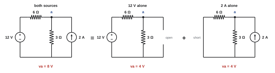
Worked problem
Superposition with two sources
A 12 V source in series with 6 Ω feeds node a; a 2 A current source also feeds node a; a 3 Ω resistor connects a to the reference. Find \(v_a\) by superposition, and check with nodal analysis.
Show solution
- Voltage source alone (current source open): a divider, \(v_a^{(1)} = 12 \times 3/(6 + 3) = 4\) V.
- Current source alone (voltage source shorted): 2 A flows into \(6 \parallel 3 = 2\) Ω, so \(v_a^{(2)} = 2 \times 2 = 4\) V.
- Total: \(v_a = 4 + 4 = 8\) V.
- Nodal check: \((v_a - 12)/6 + v_a/3 = 2\), so \(v_a - 12 + 2v_a = 12\) and \(v_a = 8\) V. ✓
Answer: \(v_a = 8\) V, with half from each source. The power in the 3 Ω resistor is \(8^2/3 = 21.3\) W, not the sum of \(4^2/3 + 4^2/3 = 10.7\) W: superposition does not apply to power.
Source transformation
A voltage source \(v_s\) in series with a resistor \(R\) is equivalent, at its terminals, to a current source \(i_s = v_s/R\) in parallel with the same resistor \(R\). Both have the same open-circuit voltage (\(v_s\)) and the same short-circuit current (\(v_s/R\)), and since both are linear, the same terminal behaviour everywhere in between. The current source arrow points toward the terminal that was the voltage source's + side.
Repeated source transformations, combined with series and parallel reduction, can simplify many circuits without writing a single simultaneous equation. The transformation does not apply to an ideal source with no series or parallel resistance, and it preserves only the terminal behaviour: the power dissipated inside the two equivalents is generally different.
Thévenin's theorem
In 1883 the French telegraph engineer Léon Charles Thévenin showed that any linear two-terminal network, however complicated, behaves at its terminals exactly like a single voltage source in series with a single resistor. The voltage is the Thévenin voltage \(V_{\text{Th}}\) and the resistor is the Thévenin resistance \(R_{\text{Th}}\).
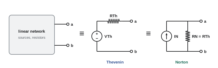
The two values are found as follows:
- \(V_{\text{Th}}\) is the open-circuit voltage \(v_{\text{oc}}\) across the terminals with the load removed.
- \(R_{\text{Th}}\) is the resistance seen looking into the terminals with all independent sources turned off (voltage sources shorted, current sources opened). If the network contains dependent sources, they stay in, and \(R_{\text{Th}}\) is found with a test source: apply a test voltage \(v_t\) (or current \(i_t\)) to the terminals, calculate the resulting current \(i_t\) (or voltage), and \(R_{\text{Th}} = v_t/i_t\).
- Alternatively, \(R_{\text{Th}} = v_{\text{oc}}/i_{\text{sc}}\), where \(i_{\text{sc}}\) is the short-circuit current with the terminals shorted. This works with or without dependent sources.
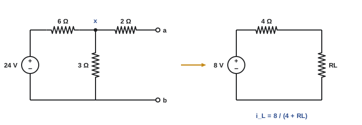
The great value of the Thévenin equivalent is that once it is found, the effect of any load can be calculated in one line: \(i_L = V_{\text{Th}}/(R_{\text{Th}} + R_L)\). Analysing a circuit for ten different loads becomes ten one-line calculations instead of ten full analyses.
Worked problem
Finding and using a Thévenin equivalent
A 24 V source in series with 6 Ω feeds node x; a 3 Ω resistor connects x to the reference; a 2 Ω resistor connects x to terminal a, with terminal b at the reference. Find the Thévenin equivalent at a-b, then the load current and power for loads of 4 Ω and 12 Ω.
Show solution
- Open circuit: no current flows in the 2 Ω, so \(v_a = v_x\). Divider: \(V_{\text{Th}} = 24 \times 3/(6 + 3) = 8\) V.
- Turn off the source (short it): looking into a-b, the 2 Ω is in series with \(6 \parallel 3 = 2\) Ω. \(R_{\text{Th}} = 2 + 2 = 4\) Ω.
- Check by short-circuit current: with a-b shorted, \(2 \parallel 3 = 1.2\) Ω, so the source sees \(6 + 1.2 = 7.2\) Ω and delivers 3.333 A; the divider sends \(3.333 \times 3/5 = 2\) A through the short. \(8/2 = 4\) Ω. ✓
- Load 4 Ω: \(i_L = 8/(4 + 4) = 1\) A, \(p_L = 1^2 \times 4 = 4\) W.
- Load 12 Ω: \(i_L = 8/(4 + 12) = 0.5\) A, \(p_L = 0.5^2 \times 12 = 3\) W.
Answer: \(V_{\text{Th}} = 8\) V and \(R_{\text{Th}} = 4\) Ω. A 4 Ω load draws 1 A (4 W); a 12 Ω load draws 0.5 A (3 W). Solving the full circuit with nodal analysis gives the same currents.
Norton's theorem
Applying a source transformation to the Thévenin equivalent gives the Norton equivalent: a current source \(I_N\) in parallel with a resistor \(R_N\). Edward Norton of Bell Labs described it in 1926. The values are
For the example above, \(I_N = 8/4 = 2\) A (matching the short-circuit current found in the check) in parallel with 4 Ω. Norton equivalents are natural when loads are connected in parallel, and they are the standard model for transistor outputs and for current-output sensors.
Thévenin resistance with a dependent source
Worked problem
Using a test source
Between terminals a and b, a 6 Ω resistor carries current \(i_x\) (from a to b). In parallel with it is a branch of a 2 Ω resistor in series with a current-controlled voltage source of \(3i_x\) volts (+ toward a). There are no independent sources. Find \(R_{\text{Th}}\).
Show solution
- With no independent sources, \(V_{\text{Th}} = 0\). Turning off sources cannot remove the dependent source, so apply a test voltage \(v_t\) across a-b.
- In the 6 Ω: \(i_x = v_t/6\).
- In the other branch: the current from a through 2 Ω and the dependent source is \((v_t - 3i_x)/2 = (v_t - v_t/2)/2 = v_t/4\).
- Test current: \(i_t = v_t/6 + v_t/4 = 5v_t/12\).
- \(R_{\text{Th}} = v_t/i_t = 12/5 = 2.4\) Ω.
Answer: 2.4 Ω, quite different from the 1.5 Ω you would get by wrongly treating the dependent source as a short. Dependent sources can even make \(R_{\text{Th}}\) negative, which is how oscillators and some amplifiers work.
Maximum power transfer
A source with Thévenin resistance \(R_{\text{Th}}\) delivers power to a load \(R_L\):
If \(R_L\) is very small, the current is large but the load voltage is nearly zero; if \(R_L\) is very large, the voltage is large but the current nearly zero. In between there is a maximum. Setting \(dp_L/dR_L = 0\) gives the maximum power transfer theorem: maximum power is delivered when
For the example, \(R_L = 4\) Ω receives \(8^2/(4 \times 4) = 4\) W, the most any load can draw from that circuit.
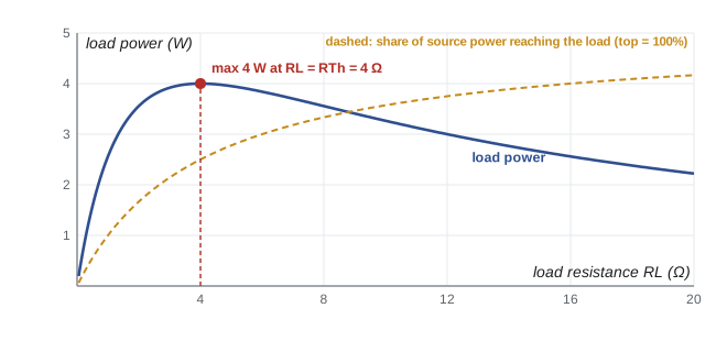
At maximum power transfer, the load and \(R_{\text{Th}}\) carry the same current and have the same resistance, so they dissipate equal power: only 50% of the power taken from the Thévenin source reaches the load. That is acceptable, even desirable, where the signal is weak and every microwatt matters: antennas, radio receivers, sensor interfaces and audio amplifiers are matched to their loads. It is never acceptable in power systems, where efficiency is everything. A utility generator or a data centre UPS is designed with a Thévenin (internal) resistance far smaller than the load, so that nearly all the power reaches the load and the voltage stays steady as the load changes.
Worked problem
Matching or efficiency?
For the 8 V, 4 Ω Thévenin source, compare a 4 Ω load and a 36 Ω load: the load power and the fraction of the equivalent source's power delivered to the load.
Show solution
- 4 Ω: \(i = 1\) A, \(p_L = 4\) W; the source delivers \(8 \times 1 = 8\) W, so 50% reaches the load.
- 36 Ω: \(i = 8/40 = 0.2\) A, \(p_L = 0.2^2 \times 36 = 1.44\) W; the source delivers \(8 \times 0.2 = 1.6\) W, so 90% reaches the load.
Answer: The matched load receives the most power (4 W) at 50% efficiency; the 36 Ω load receives far less power (1.44 W) at 90% efficiency. Which is "better" depends on whether the design goal is signal power or energy efficiency. (These fractions describe the Thévenin model; losses inside the real network can differ.)
Measuring a Thévenin equivalent
Thévenin's theorem also works experimentally, with no circuit diagram at all. Measure the open-circuit voltage with a high-resistance voltmeter: that is \(V_{\text{Th}}\). Then connect a known load resistor and measure the voltage across it; the drop tells you \(R_{\text{Th}}\) from the divider relation \(v_L = V_{\text{Th}}R_L/(R_{\text{Th}} + R_L)\). This is how the internal resistance of a battery is measured, and the same idea, applied to a power network, gives the source impedance that sets fault levels at a building's service entrance (DCE-310).
Common mistakes
MistakeAdding the powers from each source in superposition.
InsteadSuperpose voltages and currents, then compute power from the totals.
MistakeTurning off dependent sources when applying superposition or finding \(R_{\text{Th}}\).
InsteadOnly independent sources are turned off; dependent sources stay, and a test source finds \(R_{\text{Th}}\).
MistakeReplacing a turned-off current source with a short circuit.
InsteadA zero current source is an open circuit; a zero voltage source is a short.
MistakeAssuming maximum power transfer is always the design goal.
InsteadMatching gives only 50% efficiency; power systems use a load much larger than the source resistance.
MistakeMeasuring \(V_{\text{Th}}\) with the load still connected.
InsteadThe Thévenin voltage is the open-circuit voltage, with the load removed.
Summary and key terms
- In a linear circuit, responses are proportional to the sources (homogeneity) and add (additivity); power is not linear.
- The unit-output method assumes an output, works backwards, and scales.
- Superposition: sum the responses to each independent source alone; voltage sources off = short, current sources off = open; dependent sources stay.
- Source transformation: \(v_s\) in series with \(R\) ⇔ \(v_s/R\) in parallel with \(R\).
- Thévenin: \(V_{\text{Th}} = v_{\text{oc}}\); \(R_{\text{Th}}\) with sources off, or by test source, or \(v_{\text{oc}}/i_{\text{sc}}\).
- Norton: \(I_N = i_{\text{sc}} = V_{\text{Th}}/R_{\text{Th}}\) in parallel with \(R_N = R_{\text{Th}}\).
- Maximum power transfer: \(R_L = R_{\text{Th}}\), \(p_{\max} = V_{\text{Th}}^2/4R_{\text{Th}}\), at 50% efficiency.
- Power systems aim for efficiency (\(R_L \gg R_{\text{Th}}\)); signal circuits often aim for matching.
- Linear circuit
- A circuit of linear elements and independent sources, whose responses are linear functions of the sources.
- Homogeneity
- Scaling all sources by \(k\) scales every response by \(k\).
- Superposition
- The principle that a linear circuit's response to several sources is the sum of the responses to each alone.
- Source transformation
- Replacing a voltage source with series resistance by a current source with the same parallel resistance, or vice versa.
- Thévenin equivalent
- A voltage source in series with a resistor that has the same terminal behaviour as a linear network.
- Norton equivalent
- A current source in parallel with a resistor that has the same terminal behaviour as a linear network.
- Open-circuit voltage
- The voltage across a network's terminals with nothing connected.
- Short-circuit current
- The current that flows when a network's terminals are connected together.
- Test source
- A voltage or current applied to terminals to find an equivalent resistance when dependent sources are present.
- Maximum power transfer
- The condition \(R_L = R_{\text{Th}}\) under which a load receives the most power from a source.
- Impedance matching
- Designing a load to equal the source resistance (or impedance) to maximize power transfer.
- Internal resistance
- The Thévenin resistance of a real source, such as a battery or generator.
Practice problems
Work each problem on paper first, then reveal the answer to check.
In a linear circuit, a 10 V source produces 2 mA in a resistor. What current does 25 V produce?
Show answer
5 mA, by proportionality.
Convert a 9 V source with 3 Ω series resistance into a Norton (current-source) form.
Show answer
3 A in parallel with 3 Ω, with the arrow toward the original + terminal.
A 10 V source with 5 Ω feeds node a; a 1 A source also feeds a; 5 Ω connects a to the reference. Find \(v_a\) by superposition.
Show answer
From 10 V: 10 × 5/10 = 5 V. From 1 A: 1 × (5 ∥ 5) = 2.5 V. Total 7.5 V.
A network has an open-circuit voltage of 15 V and a short-circuit current of 3 A. Find its Thévenin and Norton equivalents.
Show answer
V_Th = 15 V, R_Th = 5 Ω; I_N = 3 A in parallel with 5 Ω.
Find the Thévenin equivalent at the output of a divider of 10 kΩ (top) and 10 kΩ (bottom) across 24 V. Then find the voltage on a 10 kΩ load.
Show answer
V_Th = 12 V, R_Th = 10 ∥ 10 = 5 kΩ. Load: 12 × 10/15 = 8 V, matching Lesson 2.
What load resistance draws maximum power from a source with \(V_{\text{Th}} = 20\) V and \(R_{\text{Th}} = 8\) Ω, and how much power is that?
Show answer
R_L = 8 Ω; p = 20²/(4 × 8) = 12.5 W.
A battery reads 12.6 V open-circuit and 12.0 V when supplying 30 A to a load. Estimate its internal resistance.
Show answer
R = (12.6 − 12.0)/30 = 0.02 Ω.
What is the load power and efficiency (Thévenin model) for a 2 Ω load on an 8 V, 4 Ω source?
Show answer
i = 8/6 = 1.333 A; p_L = 3.56 W; efficiency = 2/6 = 33%.
A network has a 10 Ω resistor between a and b in parallel with a VCCS of \(0.05v_{ab}\) flowing from a to b. Find \(R_{\text{Th}}\).
Show answer
With test voltage v_t: i_t = v_t/10 + 0.05v_t = 0.15v_t, so R_Th = 6.67 Ω.
Why is a UPS designed with a Thévenin resistance much smaller than its load rather than matched to it?
Show answer
Matching would waste half the power in the source and make the output voltage fall by half under load. A small source resistance gives high efficiency and a steady voltage as load changes.
Lesson quiz · 5 questions
Score 60% or more to complete this lesson.
Create a free account to save your progress, take quizzes and earn a certificate.