
ROB-200 · Lesson 12 of 12 · 28 min
Capstone: designing and debugging a robot controller board
This capstone pulls the course together by following the design and bring-up of a small robot controller board: the kind of board that sits between a mobile robot's battery, its two drive motors, its sensors and its Linux computer. You will write a requirements list, budget power and pins, sketch the architecture, learn the basics of laying out a printed circuit board so it works the first time and does not interfere with radios, use the three essential instruments, the multimeter, the oscilloscope and the logic analyzer, to bring the board up safely, and practise a systematic approach to debugging. The same process scales from a student competition robot to a commercial product.
Requirements first
Every good board starts with written requirements, which turn vague wishes into numbers you can design and test against. For our example, a differential-drive robot for indoor delivery, the requirements might read as follows. Each line will drive a design decision, and each must be checked during bring-up.
| Area | Requirement |
|---|---|
| Power input | 4S lithium-ion pack, 12.0 to 16.8 V, with reverse-polarity protection and a 15 A main fuse |
| Motors | Two brushed DC motors, 12 V nominal, 2 A running, 10 A stall; current limit at 6 A each |
| Encoders | Two quadrature encoders, 5 V, up to 100 k edges per second each, decoded in hardware |
| Rails | 5 V at 2 A for the encoders and accessories; 3.3 V at 300 mA for logic and sensors |
| Sensors | One IMU on SPI; up to four time-of-flight sensors on I2C; battery voltage and both motor currents on the ADC |
| Communication | USB to the Linux computer for micro-ROS or a custom protocol; CAN FD port for expansion |
| Safety | Hardware emergency-stop input that disables both motor drivers independently of firmware; watchdog |
| Indicators and debug | Status LEDs; SWD debug header; test points on every rail and bus |
Budgets: power, pins and peripherals
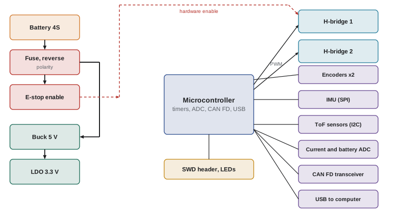
Next, budget. A power budget adds up the current on each rail at typical and worst-case load and works back to the battery through each regulator's efficiency, which tells you the regulator ratings, the fuse values and how much heat each part makes. A pin budget lists every signal and assigns it to a microcontroller pin with the right alternate function: two timers with complementary PWM for the motors, two timers in encoder mode, an SPI port, an I2C port, ADC channels, a CAN FD controller, USB and spare GPIOs for the emergency stop, fault inputs and LEDs. Doing this early, with the chip's pin-multiplexing table open, avoids discovering after the board is made that two needed functions share one pin.
loads_3v3 = {"MCU": 0.08, "IMU": 0.01, "ToF x4": 0.08, "CAN FD xcvr": 0.07, "LEDs": 0.02}
loads_5v  = {"encoders x2": 0.06, "3.3 V LDO input": sum(loads_3v3.values()), "accessories": 1.0}
i3, i5 = sum(loads_3v3.values()), sum(loads_5v.values())
p5 = 5.0 * i5
vbat_min, buck_eff = 12.0, 0.90
i_bat_logic = p5 / buck_eff / vbat_min
ldo_loss = (5.0 - 3.3) * i3
print(f"3.3 V rail: {i3*1000:.0f} mA, LDO loss {ldo_loss:.2f} W")
print(f"5 V rail: {i5:.2f} A ({p5:.1f} W)")
print(f"battery current for logic at {vbat_min} V: {i_bat_logic:.2f} A")
print(f"worst case with both motors at the 6 A limit: {i_bat_logic + 12:.1f} A")3.3 V rail: 260 mA, LDO loss 0.44 W 5 V rail: 1.32 A (6.6 W) battery current for logic at 12.0 V: 0.61 A worst case with both motors at the 6 A limit: 12.6 A
The budget confirms that a 2 A, 5 V buck converter and a small 3.3 V LDO suffice, that the LDO dissipates under half a watt, and that the 15 A main fuse leaves margin above the worst-case 12.6 A drawn when both motors hit their current limit. It also shows that the accessory allowance dominates the logic power, a prompt to ask what accessories are really planned.
Printed circuit board basics
A printed circuit board (PCB) is layers of copper on an insulating substrate, usually FR-4 glass-epoxy, with plated holes called vias connecting the layers. A two-layer board is cheap; four layers, with an inner layer devoted to a solid ground plane, make it much easier to keep signals clean and are well worth the modest extra cost for a mixed motor and logic board. Free and commercial design tools, such as KiCad, take you from schematic to layout to manufacturing files, and inexpensive fabrication services make boards in days.
Five layout rules prevent most first-board problems. First, give every current-carrying trace enough copper: trace width for a given current and acceptable temperature rise comes from charts such as IPC-2221, and motor paths may need wide pours on several layers. Second, keep a continuous ground plane under signals so every signal's return current flows directly beneath it, minimizing loop area and therefore emissions and susceptibility. Third, place decoupling capacitors at the supply pins with short connections to the plane. Fourth, keep the high-current, fast-switching loops of the motor drivers and buck converter tight and away from sensitive analogue inputs, the crystal and radio antennas. Fifth, route the current-sense amplifier inputs as a close pair straight from the shunt's pads, a Kelvin connection, so that voltage drops in the high-current copper are not measured as motor current.
def ipc2221_width_mm(current_a, temp_rise_c=10, copper_oz=1, external=True):
    """Approximate trace width from the IPC-2221 chart equations."""
    k = 0.048 if external else 0.024
    area_mil2 = (current_a / (k * temp_rise_c**0.44)) ** (1 / 0.725)
    thickness_mil = 1.378 * copper_oz
    return area_mil2 / thickness_mil * 0.0254

for i in (0.5, 2, 6, 10):
    print(f"{i:4.1f} A, 10 C rise, 1 oz outer layer: {ipc2221_width_mm(i):5.2f} mm"
f" (inner layer {ipc2221_width_mm(i, external=False):5.2f} mm)")0.5 A, 10 C rise, 1 oz outer layer: 0.12 mm (inner layer 0.30 mm) 2.0 A, 10 C rise, 1 oz outer layer: 0.78 mm (inner layer 2.03 mm) 6.0 A, 10 C rise, 1 oz outer layer: 3.56 mm (inner layer 9.25 mm) 10.0 A, 10 C rise, 1 oz outer layer: 7.19 mm (inner layer 18.71 mm)
Electromagnetic compatibility and certification
Fast edges and switching currents radiate. A robot whose motor drivers or buck converter emit strong interference can disrupt its own GPS or Wi-Fi, other equipment nearby, or fail the emissions tests a commercial product must pass. Compact switching loops, solid ground planes, slowed edges where speed is not needed, filtered cables leaving the board and metal enclosures all reduce emissions; the same measures reduce susceptibility to interference from outside, such as electrostatic discharge when someone touches the robot.
In Canada, digital devices that unintentionally emit radio energy must meet Innovation, Science and Economic Development Canada's ICES-003 standard before sale, and devices with radio transmitters such as Wi-Fi or Bluetooth must be certified under ISED's radio standards, RSS-Gen and, for 2.4 GHz modules, RSS-247. Using a pre-certified radio module, which carries its own IC certification number, greatly simplifies this; the product label then states that it contains the module's IC number. Student prototypes are not sold and need not be certified, but they must still not cause harmful interference.
Instruments: multimeter, oscilloscope, logic analyzer
Three instruments cover almost all board-level debugging. A digital multimeter measures DC and AC voltage, resistance, continuity and current. It answers static questions: is this rail at 3.3 V, is this net shorted to ground, is the CAN bus terminated with 60 Ω. An oscilloscope draws voltage against time, revealing what a multimeter averages away: ripple on a rail, ringing on an edge, a PWM waveform, a brief dip when a motor starts. A logic analyzer records many digital channels for a long time and decodes protocols, as lesson 9 described. A current-limited bench power supply is the fourth essential, because it turns a short circuit from a fire into a number on a display.
An oscilloscope must be fast enough for the signals you measure. A common rule is that its bandwidth should be at least three to five times the highest frequency of interest, and the fastest rise time it can show is about \( 0.35 / \text{BW} \). A 100 MHz oscilloscope displays rise times down to about 3.5 ns, plenty for this board. How you probe matters as much as the instrument: the long ground lead supplied with a probe forms a loop that picks up the motor driver's switching noise and adds ringing that is not really on the signal. For fast or noisy measurements, use the short ground spring that clips onto the probe tip.
Worked problem
Is the scope fast enough?
You need to check the edges on the 20 MHz SPI clock, which the IMU datasheet says should rise in no more than 5 ns. Your scope is rated at 70 MHz. Can it show whether the edges meet the specification?
Show solution
- Scope rise time: \( 0.35/70\,\text{MHz} = 5.0 \) ns.
- Measured rise time combines roughly as \( \sqrt{t_{\text{sig}}^2 + t_{\text{scope}}^2} \). A true 4 ns edge would display as \( \sqrt{16 + 25} \approx 6.4 \) ns and appear to fail.
- The scope is too slow to judge a 5 ns specification; you need at least 200 MHz, about 1.75 ns.
Answer: No. Use a scope of at least about 200 MHz, with a short ground spring on the probe.
Bring-up: powering a new board safely
Bring-up is the careful first powering of a new board. The goal is to find faults while they are still cheap. Work in stages, checking each before moving on, and keep notes. A sensible sequence for the example board is:
- Inspect the bare and assembled board under magnification for solder bridges, missing or rotated parts and the orientation of diodes, electrolytic capacitors and chips.
- With no power, measure the resistance from each rail to ground. A few ohms suggests a short or a reversed part; tens of kilohms or more is normal.
- Power the board from a bench supply at 12 V with the current limit at about 100 mA, with the motors and microcontroller-dependent loads disconnected. Check each rail's voltage and the idle current against the budget.
- Look at the buck converter's output on the oscilloscope for ripple and at its switching node for clean edges.
- Connect the SWD probe, read the microcontroller's ID, load a blink program and confirm the clock frequency by toggling a pin and measuring it.
- Test each interface separately with small test programs: read the IMU's identity register over SPI, scan the I2C bus, read the ADC channels against a multimeter, send and receive CAN frames to a USB adapter.
- Test the emergency stop and fault paths with the motors still disconnected: confirm that the e-stop removes the driver enable in hardware even while firmware commands motion.
- Finally connect one motor, raise the current limit, run it at low duty cycle and check the current reading, then the encoder, then the other motor, then both together on the battery.
Debugging systematically
When something does not work, resist random changes. Debugging is the scientific method in miniature: observe the symptom precisely, form a hypothesis about the cause, predict what a measurement will show if the hypothesis is right, measure, and narrow the search. Divide the system in half, checking signals at the midpoint, to find which half contains the fault. Compare with something known to work, such as a second board or a reference design. Change one thing at a time and write down what you did and saw. Many robot electronics faults fall into a short list of categories, and checking them first saves hours.
| Symptom | Likely causes | First check |
|---|---|---|
| Microcontroller resets when motors start | Battery sag, missing bulk capacitance, shared ground, brown-out threshold | Scope the 3.3 V rail and the battery during a motor start |
| I2C sensor not found | Wrong address, missing or doubled pull-ups, SDA and SCL swapped, sensor unpowered | Logic analyzer on SDA and SCL; check for an ACK |
| UART receives garbage | Baud rate mismatch, TX and RX swapped, no common ground, wrong logic level | Scope one byte and measure the bit width |
| ADC readings noisy or jumpy | Ground shared with motor current, no filter capacitor, aliasing of PWM ripple | Scope the ADC pin with motors on and off |
| Motor runs only one way or driver gets hot | Wrong direction logic, shoot-through, missing dead time, gate drive too low | Scope both gate signals of one half-bridge together |
| CAN frames never acknowledged | Missing termination, bit-rate mismatch, transceiver in standby, no other node | Measure 60 Ω across the bus; check the standby pin |
Capstone brief
Your capstone deliverable is a design package for a controller board meeting the requirements above, or a variation agreed with your instructor. It should contain: the requirements table with a test for each line; power, pin and bus-load budgets; an architecture diagram; a schematic of the power entry, one motor driver channel with current sensing, the battery-voltage divider and the emergency-stop path, with every component value justified by a calculation from this course; layout zoning notes; a bring-up plan with expected readings at each step; and a risk list of the three faults you consider most likely and how you would detect each. If you build the board, add your bring-up notes with measurements and oscilloscope captures, and a short reflection on what you would change in the next revision. Professional engineers rarely get a board right on the first revision; the skill is making the second one right.
Common mistakes
MistakeStarting the layout before the pin budget is complete.
InsteadAssign every function to a pin with the datasheet's multiplexing table first.
MistakePowering a new board for the first time from a battery.
InsteadUse a current-limited bench supply and bring up in stages.
MistakeBreaking the ground plane with traces or splitting it carelessly.
InsteadKeep a continuous ground plane under signals and route return paths deliberately.
MistakeMeasuring fast edges or switching noise with the long probe ground lead.
InsteadUse the short ground spring and an oscilloscope with enough bandwidth.
MistakeChanging several things at once when debugging.
InsteadForm a hypothesis, change one thing, measure and record.
Summary and key terms
- Start with numerical requirements, each paired with a test.
- Power, pin and bus budgets reveal regulator sizes, fuse values and pin conflicts before layout.
- Good layouts use adequate copper, a continuous ground plane, close decoupling, compact switching loops and Kelvin sense connections.
- Low emissions come from layout and filtering; products need EMC and radio certification before sale.
- Multimeter, oscilloscope, logic analyzer and a current-limited supply cover most debugging; scope bandwidth and probing matter.
- Bring a board up in stages, from inspection and unpowered checks to motors last.
- Debug systematically: observe, hypothesize, predict, measure, halve the search and record.
- Requirements
- Measurable statements of what a design must do, each verifiable by a test.
- Power budget
- A table of the current and power on each rail, traced back to the source.
- Pin budget
- An assignment of every signal to a microcontroller pin and function.
- PCB
- Printed circuit board: copper layers on an insulating substrate connecting components.
- Via
- A plated hole connecting copper on different PCB layers.
- Ground plane
- A continuous copper layer at ground potential providing low-impedance return paths.
- Kelvin connection
- Separate sense traces from a shunt's pads so only its own voltage drop is measured.
- EMC
- Electromagnetic compatibility: neither emitting excessive interference nor being disturbed by it.
- Oscilloscope bandwidth
- The frequency at which a scope's response falls to about 71 %; rise time ≈ 0.35 / BW.
- Bring-up
- The staged first powering and testing of a new board.
Practice problems
Work each problem on paper first, then reveal the answer to check.
Why write a test alongside each requirement?
Show answer
So that you can verify every requirement during bring-up and know when the design is done.
The 3.3 V rail draws 250 mA from a 5 V LDO input. What does the LDO dissipate?
Show answer
1.7 × 0.25 = 0.425 W.
A 5 V, 1.5 A rail is fed by a 90 % buck from a 14.4 V battery. What battery current does it draw?
Show answer
7.5 W ÷ 0.9 ÷ 14.4 ≈ 0.58 A.
Why does a four-layer board help a mixed motor and logic design?
Show answer
An inner layer can be a continuous ground plane, giving short return paths and lower noise.
What is the fastest rise time a 200 MHz oscilloscope can show?
Show answer
About 1.75 ns.
What should you measure before first applying power to a new board?
Show answer
Resistance from each rail to ground, to catch shorts.
Why set a bench supply current limit of about 100 mA at first power?
Show answer
A fault then draws only limited current instead of destroying parts.
The board resets when the motors start. What do you measure first?
Show answer
The 3.3 V rail and the battery voltage on the oscilloscope during a motor start.
What does a Kelvin connection to a shunt prevent?
Show answer
Voltage drops in the high-current copper being added to the measured shunt voltage.
Name the US and Canadian rules for unintentional emissions from digital devices.
Show answer
FCC Part 15 Subpart B; ISED ICES-003.
Lesson quiz · 5 questions
Score 60% or more to complete this lesson.
Create a free account to save your progress, take quizzes and earn a certificate.