
ROB-200 · Lesson 6 of 12 · 27 min
GPIO, pull-ups, debouncing and interrupts
General-purpose input/output (GPIO) pins are a microcontroller's simplest connection to the world. As outputs they switch LEDs, enable motor drivers and select devices; as inputs they read buttons, limit switches, bumpers, emergency-stop status and the pulses from wheel encoders. Simple as they are, GPIOs cause a surprising share of robot faults: inputs that float and read random values, switches that register ten presses instead of one, encoders that lose counts at speed, and outputs asked to supply more current than they can. This lesson explains how GPIO pins work electrically, how pull-up and pull-down resistors define idle states, how to debounce mechanical switches, and how interrupts let a microcontroller respond to events within microseconds without wasting time watching for them.
Inside a GPIO pin
Each GPIO pin connects to a small circuit that can be configured in software. As a push-pull output, two transistors drive the pin: one connects it to the supply to output a high, the other to ground for a low. As an open-drain output, only the low-side transistor is present; the pin can pull low or let go, and an external or internal resistor pulls it high when released. Open-drain outputs from several devices can share one wire safely, because no device ever drives the wire high against another driving it low, which is why I2C and many interrupt and reset lines use them. As an input, the drivers are switched off and the pin's voltage goes to a buffer, often with an optional Schmitt trigger. Most pins also have optional internal pull-up and pull-down resistors, typically 20 to 50 kΩ, and many can be connected to alternate functions such as a timer output or a UART.
Output pins can source or sink only limited current, often 4 to 20 mA per pin, with a lower limit for the whole chip or for each group of pins. As the current rises, the output voltage moves away from the rail because of the transistors' resistance. Driving an LED at a few milliamperes is fine; driving a relay, a motor or a long LED strip directly is not. Use the switching circuits from lesson 3, and treat datasheet absolute maximum ratings as limits never to approach, not targets.
Floating inputs and pull resistors
An input pin connected to nothing is floating. Its input impedance is extremely high, so it picks up stray charge and nearby signals, reading 0 or 1 at random and sometimes oscillating, which wastes power and produces phantom button presses. Every input must be driven to a defined level at all times. A pull-up resistor connects the input to the supply, so it reads 1 until a switch connects it to ground; a pull-down does the opposite. The pull-up arrangement with the switch to ground is the most common, which makes the input active-low: pressed reads 0.
Choosing the resistor is a trade-off. When the switch is closed, the resistor draws \( V/R \) continuously, so lower values waste more power: 3.3 V across 1 kΩ is 3.3 mA. Higher values save power but make the input more sensitive to noise and slower to return high, because the pin and wire capacitance must charge through the resistor. Values of 4.7 to 10 kΩ are typical for switches on a robot; the internal 20 to 50 kΩ pull-ups are fine for buttons on a board but marginal for long wires to a bumper on the far side of a chassis.
Worked problem
Pull-up current and rise time
A limit switch on a robot arm is wired with 1.5 m of cable, about 150 pF, to a 3.3 V input with VIH = 2.3 V. Compare a 40 kΩ internal pull-up with a 4.7 kΩ external one.
Show solution
- Current with the switch closed: \( 3.3/40\,000 = 83\ \mu\text{A} \) internal; \( 3.3/4\,700 = 0.70 \) mA external.
- Time to rise from 0 to VIH: \( t = -RC\ln(1 - 2.3/3.3) = 1.19\,RC \).
- Internal: \( 1.19 \times 40\,000 \times 150 \times 10^{-12} \approx 7.1\ \mu\text{s} \). External: about 0.84 µs.
- Both are fast enough for a switch, but the stiffer external pull-up holds the line more firmly against noise coupled from nearby motor wires.
Answer: Use the 4.7 kΩ external pull-up for the long cable; the 0.7 mA it draws when closed is negligible on a robot.
Switch bounce
When a mechanical switch closes, its contacts do not meet cleanly. They bounce apart and together several times over a few hundred microseconds to several milliseconds, so the input sees a burst of transitions. A program counting presses or reacting to each edge sees many events instead of one. Bumpers, limit switches, buttons and reed switches all bounce. Debouncing fixes this, either in hardware with a resistor-capacitor filter followed by a Schmitt-trigger input, or in software by requiring the input to be stable for a set time before accepting a change.
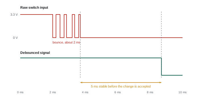
A common software approach samples the input at a fixed rate, say every millisecond from a timer, and changes the reported state only after the raw reading has differed from it for a set number of consecutive samples. The listing below simulates this on a recorded bouncy press and release, sampled every millisecond, and compares a naive edge counter with a debouncer that needs five stable samples.
# 1 = released (pull-up), 0 = pressed. One sample per millisecond.
raw = ([1]*5 + [0,1,0,0,1,0,1,0,0,0] + [0]*20 +     # bouncy press
       [1,0,1,1,0,1,1,1] + [1]*15)                  # bouncy release

naive_presses = sum(1 for a, b in zip(raw, raw[1:]) if a == 1 and b == 0)

def debounce(samples, needed=5):
    state, count, events = samples[0], 0, []
    for t, s in enumerate(samples):
        if s != state:
            count += 1
            if count >= needed:
                state, count = s, 0
                events.append((t, "pressed" if s == 0 else "released"))
        else:
            count = 0
    return events

print("naive falling edges:", naive_presses)
for t, what in debounce(raw):
print(f"debounced: {what} at t = {t} ms")naive falling edges: 6 debounced: pressed at t = 16 ms debounced: released at t = 44 ms
The naive counter sees six presses; the debouncer reports one press and one release, each a few milliseconds after the switch has settled. Five milliseconds of delay is unnoticeable for a button and acceptable for most bumpers, but too slow for something like a homing switch on a fast axis, where a hardware filter or a better sensor such as an optical or Hall-effect switch, which does not bounce, is the better choice. Safety inputs such as emergency-stop chains should be handled by dedicated hardware rather than debounced in software.
Polling and interrupts
A program can find out about an input change in two ways. Polling reads the pin regularly in the main loop or a timer task. It is simple, predictable and fine for slow signals such as buttons, but it can miss short pulses and wastes time checking pins that rarely change. An interrupt makes the hardware watch the pin and, on a configured edge, pause the main program, run a short function called an interrupt service routine (ISR), and return. Interrupt latency, the delay from the edge to the first instruction of the ISR, is typically well under a microsecond on a Cortex-M microcontroller, so interrupts are the tool for fast or rare events: encoder pulses, a data-ready signal from a sensor, a fault output from a motor driver.
ISRs must be short. While one runs, other interrupts of equal or lower priority wait, and the main program is frozen. The rule is to do the minimum in the ISR, such as recording a timestamp, incrementing a counter or setting a flag, and leave the processing to the main loop or a task. Variables shared between an ISR and the main program must be volatile, and multi-byte values must be read with interrupts briefly disabled, or by other atomic means, so the main program never sees half of an old value and half of a new one. Interrupt priorities, configured in the interrupt controller (the NVIC on Arm Cortex-M), let urgent events such as a motor-driver fault pre-empt less urgent ones.
#include <stdint.h>
#include <stdbool.h>

static volatile int32_t  g_count = 0;     /* encoder position */
static volatile bool     g_fault = false;

/* Called on every edge of encoder channel A (both edges enabled). */
void EXTI0_IRQHandler(void) {
    exti_clear_flag(0);
    bool a = gpio_read(ENC_A), b = gpio_read(ENC_B);
    g_count += (a == b) ? -1 : +1;          /* direction from phase */
}

/* Motor driver fault output, active low: highest priority. */
void EXTI1_IRQHandler(void) {
    exti_clear_flag(1);
    motor_disable_all();                     /* act immediately */
    g_fault = true;                          /* report to main loop */
}

int32_t encoder_read(void) {
    __disable_irq();                         /* read atomically */
    int32_t c = g_count;
    __enable_irq();
    return c;
}
Quadrature encoders
Wheel and joint encoders usually produce two square waves, channels A and B, a quarter cycle apart, in quadrature. The order of the edges tells the direction: if A leads B the shaft turns one way, if B leads A the other. Counting every edge on both channels, called 4× decoding, gives four counts per cycle. An encoder rated at 500 cycles per revolution therefore gives 2,000 counts per revolution with 4× decoding. Many robots mount the encoder on the motor shaft before the gearbox, multiplying the resolution at the wheel by the gear ratio.
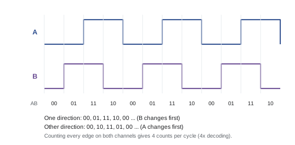
The edge rate determines whether the microcontroller can keep up. At speed, an interrupt per edge can overwhelm the processor, so serious motor controllers use timer peripherals with built-in quadrature decoder modes that count edges in hardware, with no software involvement, as lesson 7 notes.
Worked problem
Can interrupts keep up?
A motor turns at 6,000 rpm with a 1,024-cycle-per-revolution encoder on its shaft, decoded 4×. Each interrupt takes about 0.8 µs including entry and exit. What fraction of the processor does counting use, and what is the resolution at the wheel after a 20:1 gearbox?
Show solution
- Revolutions per second: \( 6000/60 = 100 \).
- Edges per second: \( 100 \times 1024 \times 4 = 409\,600 \).
- CPU time: \( 409\,600 \times 0.8\ \mu\text{s} \approx 0.33 \) s per second, a third of the processor.
- Wheel resolution: \( 1024 \times 4 \times 20 = 81\,920 \) counts per wheel revolution.
Answer: About 33 % of the CPU, too much. Use a timer's hardware quadrature mode, which costs no CPU time; the wheel resolution is 81,920 counts per revolution.
def edge_rate(rpm, cpr, decoding=4):
    return rpm / 60 * cpr * decoding

for rpm in (300, 3000, 6000, 12000):
    rate = edge_rate(rpm, 1024)
    print(f"{rpm:6d} rpm -> {rate/1000:7.1f} k edges/s, "
f"CPU at 0.8 us each: {rate*0.8e-6*100:5.1f} %")300 rpm -> 20.5 k edges/s, CPU at 0.8 us each: 1.6 % 3000 rpm -> 204.8 k edges/s, CPU at 0.8 us each: 16.4 % 6000 rpm -> 409.6 k edges/s, CPU at 0.8 us each: 32.8 % 12000 rpm -> 819.2 k edges/s, CPU at 0.8 us each: 65.5 %
Common mistakes
MistakeLeaving an unused or unconnected input floating.
InsteadEnable a pull resistor or tie the pin to a defined level.
MistakeDriving relays, motors or many LEDs straight from GPIO pins.
InsteadRespect per-pin and total current limits; use transistor switches.
MistakeCounting raw edges from a mechanical switch.
InsteadDebounce in hardware or software, or use a non-contact sensor.
MistakeDoing heavy work, delays or printing inside an interrupt service routine.
InsteadKeep ISRs short: record, count or flag, and process in the main loop.
MistakeUsing software interrupts per edge for a fast encoder.
InsteadUse the timer's hardware quadrature decoder.
Summary and key terms
- GPIO pins can be push-pull or open-drain outputs, or inputs with optional pull resistors and Schmitt triggers.
- Output pins supply only a few milliamperes; use switching circuits for real loads.
- Floating inputs read randomly; pull-ups or pull-downs set a defined idle level.
- Lower pull resistor values resist noise and rise faster but draw more current when the switch is closed.
- Mechanical switches bounce for milliseconds; debounce with an RC filter and Schmitt trigger or a stable-sample count.
- Interrupts respond within microseconds; keep ISRs short and protect shared variables.
- Quadrature encoders give direction and 4× resolution; high edge rates need hardware decoding.
- GPIO
- General-purpose input/output pin configurable in software.
- Push-pull output
- An output that actively drives both high and low.
- Open-drain output
- An output that can only pull low; a resistor pulls the line high.
- Floating input
- An input not driven to any defined level, which reads unpredictably.
- Pull-up resistor
- A resistor that holds a line high unless something pulls it low.
- Contact bounce
- The rapid make-and-break of switch contacts when they open or close.
- Debouncing
- Filtering out bounce so that one switch action produces one event.
- Interrupt service routine
- A function the hardware runs automatically when an interrupt occurs.
- Interrupt latency
- The delay between an event and the start of its interrupt service routine.
- Quadrature encoder
- A sensor producing two phase-shifted pulse trains that encode position and direction.
Practice problems
Work each problem on paper first, then reveal the answer to check.
Why do I2C lines use open-drain outputs?
Show answer
Several devices can share a line without one driving high while another drives low.
A 10 kΩ pull-up to 3.3 V is shorted to ground by a switch. What current flows?
Show answer
0.33 mA.
With the pull-up wired to the supply and the switch to ground, what does the pin read when pressed?
Show answer
0; the input is active-low.
Why might an internal 40 kΩ pull-up be unreliable on a 2 m bumper cable?
Show answer
The weak pull-up lets noise coupled into the cable change the reading.
A debouncer samples every 2 ms and needs 4 stable samples. What is the minimum delay before a change is reported?
Show answer
About 8 ms after the input settles.
Give two things that should not happen inside an ISR.
Show answer
Long calculations, delays, printing, waiting for other peripherals.
Why disable interrupts briefly when reading a 32-bit counter on an 8-bit microcontroller?
Show answer
The read takes several instructions, and an interrupt could change the value midway.
A 360-cycle encoder decoded 4× gives how many counts per revolution?
Show answer
1,440.
How do you tell direction from quadrature signals?
Show answer
From which channel leads; equivalently, the order of the A and B states.
An encoder produces 200,000 edges per second. Should you use per-edge interrupts?
Show answer
No; use a hardware quadrature counter.
Lesson quiz · 5 questions
Score 60% or more to complete this lesson.
Create a free account to save your progress, take quizzes and earn a certificate.