
ROB-200 · Lesson 8 of 12 · 26 min
Analogue inputs: ADCs, sensors and signal conditioning
Many robot sensors produce analogue voltages: potentiometers on joints, current-sense amplifiers in motor drivers, battery voltage dividers, force-sensitive resistors in grippers, infrared distance sensors, thermistors on motors and analogue microphones. The microcontroller's analogue-to-digital converter (ADC) turns these voltages into numbers. Getting a trustworthy number requires understanding what the ADC actually measures, how its resolution and reference set the smallest change it can see, how sampling works and what goes wrong when it is done carelessly, and how to condition the signal with dividers, amplifiers and filters so it arrives at the ADC in a form it can measure accurately.
What an ADC does
An ADC compares an input voltage with a reference voltage and outputs a number proportional to their ratio. An N-bit ADC divides the reference range into 2^N steps. Microcontroller ADCs are commonly 10 or 12 bits, and some reach 16; dedicated external converters offer 16 to 24 bits for precise measurements such as load cells. The size of one step, the least significant bit (LSB), is the smallest change the ADC can distinguish:
A 12-bit ADC with a 3.3 V reference has 4,096 codes and an LSB of about 0.81 mV. Resolution is not accuracy. Real converters add offset error, gain error, non-linearity and noise, so the last bit or two of a microcontroller ADC reading usually flicker, and the effective number of bits, ENOB, may be 9 to 11 rather than 12. The reference itself sets the accuracy ceiling: if the 3.3 V supply used as the reference is really 3.25 V, every reading is 1.5 % off. Precise designs use a dedicated reference chip, or measure ratiometrically, powering a sensor such as a potentiometer from the same voltage that serves as the ADC reference, so supply variations cancel.
def adc_code(vin, vref=3.3, bits=12):
    code = int(vin / vref * 2**bits)
    return max(0, min(code, 2**bits - 1))

def adc_volts(code, vref=3.3, bits=12):
    return code / 2**bits * vref

for bits in (8, 10, 12, 16):
    print(f"{bits:2d}-bit: LSB = {3.3 / 2**bits * 1000:7.3f} mV")

v = 1.2345
c = adc_code(v)
print(f"{v} V -> code {c} -> {adc_volts(c):.4f} V (error {abs(adc_volts(c)-v)*1000:.2f} mV)")
print(f"same code read with a 3.25 V true reference: {adc_volts(c, vref=3.25):.4f} V")8-bit: LSB = 12.891 mV 10-bit: LSB = 3.223 mV 12-bit: LSB = 0.806 mV 16-bit: LSB = 0.050 mV 1.2345 V -> code 1532 -> 1.2343 V (error 0.22 mV) same code read with a 3.25 V true reference: 1.2156 V
Sampling and aliasing
An ADC measures the input at discrete moments, the sampling rate. To represent a signal faithfully, the sampling rate must exceed twice the highest frequency present, the Nyquist criterion. Frequencies above half the sampling rate do not disappear: they fold back and appear as false, lower frequencies in the data, an effect called aliasing. A current-sense signal with 20 kHz PWM ripple sampled at 1 kHz, for example, shows a slow wobble that is not really there, and no amount of software filtering afterwards can tell the alias from a real signal.
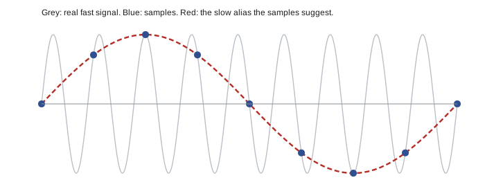
The defence is an anti-aliasing filter, a low-pass filter before the ADC that removes content above half the sampling rate. In robots, a simple resistor-capacitor filter is often enough. For motor current, there is a cleverer solution: trigger the ADC from the PWM timer so it samples at the same point in every PWM cycle, typically the middle of the on-time, where the current equals its average. This synchronized sampling is standard in motor controllers and lesson 11 returns to it.
Worked problem
Spotting an alias
A robot logs a motor's current at 1 kHz. The motor's PWM runs at 20.05 kHz, and its ripple leaks into the measurement. What frequency appears in the log?
Show solution
- Find the multiple of 1 kHz nearest 20.05 kHz: 20 kHz (k = 20).
- \( f_{\text{alias}} = |20.05 - 20| = 0.05 \) kHz = 50 Hz.
- The log shows a 50 Hz oscillation, which could easily be mistaken for mains interference or a mechanical vibration.
Answer: 50 Hz. Filter before the ADC, or synchronize sampling with the PWM.
Resistive sensors and dividers
Many sensors change resistance: potentiometers, thermistors, force-sensitive resistors, light-dependent resistors and strain gauges. Placing the sensor in a voltage divider, as in lesson 1, converts resistance to a voltage. A potentiometer used as a joint sensor is already a divider: with its ends across the reference voltage, the wiper voltage is proportional to the angle. For a thermistor, whose resistance falls steeply with temperature, the divider produces a non-linear voltage that software converts with the manufacturer's Beta value or the Steinhart-Hart equation. Choose the fixed resistor near the sensor's resistance in the middle of the range of interest to get the greatest sensitivity there.
import math
R_FIXED, R0, T0, BETA = 10_000, 10_000, 298.15, 3950   # 10k NTC, B = 3950 K

def thermistor_temp(code, bits=12):
    """Thermistor on the bottom of a divider, fixed resistor to Vref."""
    ratio = code / (2**bits - 1)
    r = R_FIXED * ratio / (1 - ratio)
    inv_t = 1 / T0 + math.log(r / R0) / BETA
    return 1 / inv_t - 273.15, r

for code in (3000, 2048, 1200, 700):
    t, r = thermistor_temp(code)
print(f"code {code:4d}: R = {r/1000:6.2f} kOhm, T = {t:5.1f} C")code 3000: R = 27.40 kOhm, T = 3.9 C code 2048: R = 10.00 kOhm, T = 25.0 C code 1200: R = 4.15 kOhm, T = 46.2 C code 700: R = 2.06 kOhm, T = 65.3 C
Strain gauges, used in load cells for force and weight, change resistance by only a fraction of a per cent. They are wired in a Wheatstone bridge, two dividers side by side, so the output is the small difference between two voltages, measured by an instrumentation amplifier or a dedicated bridge ADC chip such as the 24-bit converters common on load-cell boards.
Amplifiers and op-amps
Some signals are too small for the ADC to resolve, and some are too large or centred in the wrong place. Operational amplifiers (op-amps) scale and shift them. An op-amp has very high gain and, with feedback resistors, forms amplifiers whose gain is set by the resistor ratio. A non-inverting amplifier has gain 1 + Rf/Rg; a voltage follower, with gain 1, buffers a high-impedance source such as a divider so the ADC's input does not load it. Op-amps for single-supply robot circuits should be rail-to-rail types, whose inputs and outputs can swing close to 0 V and the supply.
Motor current is commonly measured with a small sense resistor, a shunt of a few milliohms, in the current path. The voltage across it is tiny, so a current-sense amplifier, an op-amp circuit integrated with precise gain, amplifies it. Some sense the low side between the load and ground; others, the high side, can measure in the supply line and often both directions. Hall-effect current sensors measure the magnetic field around a conductor instead, giving isolation and no power loss in a resistor, at somewhat lower accuracy.
Worked problem
Designing a current-sense chain
A drive motor draws up to 20 A. A 2 mΩ shunt and a current-sense amplifier with a gain of 50 feed a 12-bit, 3.3 V ADC. The amplifier output is offset to 1.65 V at zero current so it can show both directions. What is the measurement range and resolution, and how much power does the shunt waste?
Show solution
- Shunt voltage at 20 A: \( 20 \times 0.002 = 40 \) mV. Amplified: \( 40 \times 50 = 2.0 \) V, which exceeds the 1.65 V of headroom above the offset.
- The range is \( \pm 1.65/(0.002 \times 50) = \pm 16.5 \) A, too small. Reducing the gain to 40 gives \( \pm 20.6 \) A, enough.
- With gain 40: 1 LSB = 0.81 mV at the ADC = \( 0.81 / 40 / 0.002 \approx 10 \) mA of motor current.
- Shunt loss at 20 A: \( 20^2 \times 0.002 = 0.8 \) W, so it needs a 2 W or larger rating.
Answer: With a gain of 40, the range is about ±20.6 A with roughly 10 mA resolution; the shunt dissipates 0.8 W at full current.
Filtering
A first-order RC low-pass filter, a series resistor followed by a capacitor to ground, passes slow changes and attenuates fast ones. Its cut-off frequency, where the output has fallen to about 71 % (−3 dB) of the input, is:
Above \( f_c \), the output falls by a factor of ten for each tenfold increase in frequency, 20 dB per decade, which is gentle; steep anti-aliasing needs higher-order active filters, but for robot sensors a single RC stage plus software filtering usually works. The capacitor also helps the ADC directly: many microcontroller ADCs charge a small internal sampling capacitor from the input during a short acquisition time, and a source with high resistance cannot charge it in time, giving low readings. A capacitor of a few nanofarads at the ADC pin, or a buffer amplifier, supplies that charge. Check the datasheet's maximum source impedance for your chosen sampling time.
Software adds further filtering. A moving average of the last N samples reduces random noise by a factor of about the square root of N. An exponential filter, y = y + α(x − y), needs only one stored value and is common in firmware. Oversampling, taking many samples and averaging, can even increase effective resolution when enough noise is present to dither the readings. But every filter adds delay, and delay in a feedback loop reduces stability, so control engineers filter as little as necessary and account for the lag, as ROB-300 explains.
import math, random
random.seed(1)
def rc_cutoff(r, c): return 1 / (2 * math.pi * r * c)
print(f"1 kOhm and 10 nF: fc = {rc_cutoff(1e3, 10e-9)/1000:.1f} kHz")
print(f"10 kOhm and 100 nF: fc = {rc_cutoff(1e4, 100e-9):.0f} Hz")

true_v = 2.000
samples = [true_v + random.gauss(0, 0.010) for _ in range(256)]
alpha, y = 0.1, samples[0]
for x in samples:
    y += alpha * (x - y)
spread = max(samples) - min(samples)
avg16 = sum(samples[-16:]) / 16
print(f"raw spread: {spread*1000:.1f} mV")
print(f"average of 16: {avg16:.4f} V, exponential filter: {y:.4f} V")1 kOhm and 10 nF: fc = 15.9 kHz 10 kOhm and 100 nF: fc = 159 Hz raw spread: 55.7 mV average of 16: 2.0003 V, exponential filter: 2.0023 V
Common mistakes
MistakeTreating ADC resolution as accuracy.
InsteadAccount for reference error, offset, gain error and noise; calibrate against a known input.
MistakeSampling a signal with fast content without an anti-aliasing filter.
InsteadLow-pass filter below half the sampling rate, or synchronize sampling with the PWM.
MistakeConnecting a high-resistance divider straight to an ADC pin with a short sampling time.
InsteadAdd a capacitor at the pin, a buffer amplifier, or a longer acquisition time.
MistakeUsing the noisy logic supply as the ADC reference for precise measurements.
InsteadUse a dedicated reference, or measure ratiometrically.
MistakeAdding heavy software filtering inside a control loop without considering delay.
InsteadFilter only as much as needed and include the lag in the controller design.
Summary and key terms
- An N-bit ADC divides the reference into 2^N codes; one LSB is Vref / 2^N.
- Real ADCs have noise and errors, so effective resolution is less than nominal; the reference limits accuracy.
- Sample faster than twice the highest frequency present or aliases appear; filter first.
- Resistive sensors become voltages through dividers or bridges; convert non-linear sensors in software.
- Op-amps scale, offset and buffer signals; current-sense amplifiers measure motor current via shunts.
- An RC low-pass filter has fc = 1/(2πRC) and also helps the ADC's sampling capacitor charge.
- Software averaging and exponential filters reduce noise at the cost of delay.
- ADC
- Analogue-to-digital converter, which turns a voltage into a number.
- LSB
- Least significant bit; the voltage represented by one ADC step.
- ENOB
- Effective number of bits, the resolution actually achieved after noise and errors.
- Reference voltage
- The voltage against which an ADC measures its input.
- Ratiometric measurement
- Powering a sensor from the ADC reference so supply variations cancel.
- Nyquist criterion
- The requirement to sample at more than twice the highest signal frequency.
- Aliasing
- False low-frequency content created by sampling a signal too slowly.
- Shunt resistor
- A small, precise resistor whose voltage drop measures current.
- Op-amp
- A high-gain amplifier used with feedback to build precise amplifiers and filters.
- Cut-off frequency
- The frequency at which a filter's output falls to about 71 % of its input.
Practice problems
Work each problem on paper first, then reveal the answer to check.
What is the LSB of a 10-bit ADC with a 5 V reference?
Show answer
About 4.9 mV.
A 12-bit, 3.3 V ADC reads 2,482. What voltage is that?
Show answer
About 2.0 V.
A signal contains up to 400 Hz. What minimum sampling rate avoids aliasing?
Show answer
More than 800 Hz; in practice several times that.
A 9.8 kHz vibration is sampled at 10 kHz. What alias appears?
Show answer
200 Hz.
A non-inverting amplifier has Rf = 39 kΩ and Rg = 1 kΩ. What is its gain?
Show answer
40.
A 5 mΩ shunt carries 8 A. What voltage does it develop and what power does it dissipate?
Show answer
40 mV and 0.32 W.
What is the cut-off of a 4.7 kΩ and 100 nF RC filter?
Show answer
About 339 Hz.
Why measure a potentiometer ratiometrically?
Show answer
Changes in the supply affect sensor and reference equally, so the reading is unchanged.
Averaging 64 samples of random noise reduces it by roughly what factor?
Show answer
About 8.
Why does a high source resistance cause low ADC readings?
Show answer
The internal sampling capacitor cannot charge fully during the acquisition time.
Lesson quiz · 5 questions
Score 60% or more to complete this lesson.
Create a free account to save your progress, take quizzes and earn a certificate.