
ROB-210 · Lesson 6 of 12 · 30 min
Forward kinematics of robot arms
Forward kinematics answers the most basic question a robot controller asks thousands of times a second: given the current joint readings, where is the tool and which way does it face? The answer feeds the display on the teach pendant, collision checking, Cartesian motion control, safety functions that limit tool speed near people, and the inverse kinematics solvers of the next lessons. This lesson applies the Denavit–Hartenberg method to real arm architectures: the planar arms already met, the anthropomorphic elbow arm, the spherical wrist and a complete six-axis collaborative robot. It also covers tool transforms, URDF models, and the difference between what the kinematic model predicts and where the physical tool actually is.
The forward kinematics recipe
For a serial arm described by a DH table, forward kinematics is a product of link transforms followed by any fixed tool transform:
Often a base transform is added in front, \( {}^{W}T_{0} \), to place the robot in the world or on a mobile platform. The result is a 4 × 4 matrix whose upper-left 3 × 3 block is the tool orientation and whose last column holds the tool position. Forward kinematics always has exactly one answer, it is cheap to compute (a six-axis arm needs a few hundred floating-point operations), and it can be evaluated in microseconds, which is why controllers run it at every servo cycle.
The recipe is mechanical, but each step hides a choice that matters in practice: where the base frame sits (the floor, the mounting flange or the first joint), what zero position the DH angles correspond to compared with the controller's joint zero, and where the tool frame is. Agreeing on these three conventions with the rest of the system is as important as getting the trigonometry right.
The anthropomorphic (elbow) arm
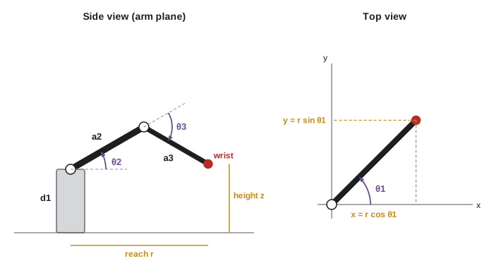
The most common industrial arm architecture resembles a human arm: a waist joint rotating about a vertical axis, a shoulder and an elbow with parallel horizontal axes, then a wrist. The first three joints, often called the arm or regional structure, position the wrist; the last three, the wrist, orient the tool. For the first three joints, with the shoulder at height \( d_1 \) above the base, upper arm length \( a_2 \) and forearm length \( a_3 \), a standard DH table is:
| Link i | \( \theta_i \) | \( d_i \) | \( a_i \) | \( \alpha_i \) |
|---|---|---|---|---|
| 1 (waist) | \( \theta_1 \) | \( d_1 \) | 0 | 90° |
| 2 (shoulder) | \( \theta_2 \) | 0 | \( a_2 \) | 0 |
| 3 (elbow) | \( \theta_3 \) | 0 | \( a_3 \) | 0 |
The 90° twist at link 1 turns the vertical waist axis into the horizontal shoulder axis. Multiplying the three transforms gives the position of the end of the forearm:
The structure is easy to interpret: the shoulder and elbow form a planar 2R arm in a vertical plane, giving a horizontal reach \( r = a_2 c_2 + a_3 c_{23} \) and a height, and the waist swings that plane around the vertical axis by \( \theta_1 \). This decomposition is exactly what makes the inverse kinematics of elbow arms solvable in closed form in lesson 8.
Worked problem
Reach of an elbow arm
An elbow arm has \( d_1 = 0.30 \), \( a_2 = 0.40 \) and \( a_3 = 0.35 \) m. Find the wrist centre position for \( \theta_1 = 45^\circ \), \( \theta_2 = 30^\circ \), \( \theta_3 = -60^\circ \).
Show solution
- \( \theta_2 + \theta_3 = -30^\circ \). Horizontal reach: \( r = 0.40\cos 30^\circ + 0.35\cos(-30^\circ) = 0.346 + 0.303 = 0.650 \) m.
- Height: \( z = 0.30 + 0.40\sin 30^\circ + 0.35\sin(-30^\circ) = 0.30 + 0.20 - 0.175 = 0.325 \) m.
- Swing by 45°: \( x = y = 0.650 \times 0.707 = 0.460 \) m.
Answer: The wrist centre is at about (0.460, 0.460, 0.325) m. The elbow is bent down 60° relative to the upper arm, so the forearm slopes 30° below horizontal.
The spherical wrist
A wrist is spherical when its three joint axes intersect at a single point, the wrist centre. Most six-axis industrial arms are designed this way, often with a roll-pitch-roll arrangement whose orientation is described by Z-Y-Z Euler angles. The great advantage is kinematic decoupling: the wrist joints change the tool's orientation but not the position of the wrist centre. So the position of the wrist centre depends only on the first three joints, and the tool position follows by adding the tool length along the approach direction:
Decoupling turns a hard six-joint problem into two easier three-joint problems, position then orientation, and it is the main reason classic industrial arms have closed-form inverse kinematics. Collaborative arms such as the Universal Robots series, and many lightweight designs, use an offset wrist in which the wrist axes do not all meet. That simplifies the mechanical design and allows continuous rotation, but it loses the clean decoupling, so their inverse kinematics is more involved.
A complete example: a six-axis collaborative arm
Universal Robots publishes standard DH parameters for its arms. For the UR5e, a widely used collaborative robot with a reach of about 850 mm, the published values are:
| Joint | \( d_i \) (m) | \( a_i \) (m) | \( \alpha_i \) |
|---|---|---|---|
| 1 Base | 0.1625 | 0 | 90° |
| 2 Shoulder | 0 | −0.425 | 0 |
| 3 Elbow | 0 | −0.3922 | 0 |
| 4 Wrist 1 | 0.1333 | 0 | 90° |
| 5 Wrist 2 | 0.0997 | 0 | −90° |
| 6 Wrist 3 | 0.0996 | 0 | 0 |
The negative link lengths reflect the frame choices that make the robot's zero position, all joints at zero, a straight horizontal arm. The offsets \( d_4 \), \( d_5 \) and \( d_6 \) show that the wrist is not spherical. Feeding the table into the DH function from lesson 5 gives the flange pose; the code below evaluates it at the zero position and at a typical working pose.
import numpy as np
np.set_printoptions(precision=4, suppress=True)
def dh(theta, d, a, alpha):
    ct, st, ca, sa = np.cos(theta), np.sin(theta), np.cos(alpha), np.sin(alpha)
    return np.array([[ct,-st*ca,st*sa,a*ct],[st,ct*ca,-ct*sa,a*st],[0,sa,ca,d],[0,0,0,1]])
D = [0.1625, 0, 0, 0.1333, 0.0997, 0.0996]
A = [0, -0.425, -0.3922, 0, 0, 0]
ALPHA = [np.pi/2, 0, 0, np.pi/2, -np.pi/2, 0]
def ur5e_fk(q):
    T = np.eye(4)
    for i in range(6): T = T @ dh(q[i], D[i], A[i], ALPHA[i])
    return T
print("zero pose flange position:", ur5e_fk([0]*6)[:3,3])
q = np.radians([0, -90, 90, -90, -90, 0])
T = ur5e_fk(q)
print("working pose flange position:", T[:3,3])
print("flange z-axis (approach): ", T[:3,2])zero pose flange position: [-0.8172 -0.2329 0.0628] working pose flange position: [-0.4919 -0.1333 0.4879] flange z-axis (approach): [ 0. -0. -1.]
At the zero pose the flange lies 0.817 m out along the negative x-axis, the sum of the two link lengths, with the wrist offsets shifting it 0.233 m sideways and leaving it 0.063 m above the base frame. The second pose, a common 'home' configuration, folds the arm so the tool points straight down, as the approach vector (0, 0, −1) confirms. Comparing such outputs with the pose shown on the robot's pendant is a quick way to confirm that the table, the joint zeros and the sign conventions match.
Tool frames and the tool centre point
The last DH frame usually sits on the mounting flange. The tool itself, a gripper, a suction cup, a welding torch, adds a fixed transform from the flange to the tool centre point (TCP). Controllers let you define several TCPs and switch between them, because the same arm may carry a tool changer or a dual gripper. Getting the TCP right matters: an orientation error in the TCP definition makes the tool tip swing in an arc when the robot reorients around what it believes is the tip.
A TCP is often calibrated by touching a fixed sharp point with the tool tip from four or more different orientations. Each touch gives the equation \( R_k\,\mathbf{t} + \mathbf{p}_k = \mathbf{c} \), where \( R_k \) and \( \mathbf{p}_k \) are the flange orientation and position from forward kinematics, \( \mathbf{t} \) is the unknown tool offset in the flange frame and \( \mathbf{c} \) the unknown fixed point. Subtracting pairs of equations eliminates \( \mathbf{c} \) and leaves a linear least-squares problem for \( \mathbf{t} \).
Worked problem
Adding a tool offset
A gripper's fingertip centre is 0.15 m along the flange z-axis. At the working pose above, the flange is at about \( (-0.4919, -0.1333, 0.4879) \) m with its z-axis pointing straight down. Where is the TCP?
Show solution
- Tool transform: translation \( (0, 0, 0.15) \) in the flange frame, no rotation.
- In the base frame, the offset is \( 0.15\,\hat{\mathbf{z}}_6 = 0.15 \times (0, 0, -1) = (0, 0, -0.15) \).
- TCP: \( (-0.4919, -0.1333, 0.4879 - 0.15) = (-0.4919, -0.1333, 0.3379) \) m.
Answer: The TCP is 0.15 m below the flange, at about (−0.492, −0.133, 0.338) m. Forgetting the tool transform would make every target 15 cm too high, or crash the gripper into the table.
URDF models in ROS
ROS describes robots with the Unified Robot Description Format (URDF), an XML file listing links and joints. Each joint has a type (revolute, prismatic, continuous or fixed), a parent and child link, an origin transform written as xyz and rpy, and an axis vector. The robot_state_publisher node reads the URDF and the current joint states and broadcasts every link's transform to tf2 by exactly the forward kinematics chain described in this lesson. MoveIt uses the same model for planning and collision checking. Converting a DH table to URDF is straightforward, because each DH row is a fixed transform followed by a joint motion; manufacturers usually supply ready-made URDF or xacro files generated from their CAD models.
<joint name="elbow_joint" type="revolute">
  <parent link="upper_arm_link"/>
  <child link="forearm_link"/>
  <origin xyz="-0.425 0 0" rpy="0 0 0"/>
  <axis xyz="0 0 1"/>
  <limit lower="-3.14159" upper="3.14159" effort="150" velocity="3.14"/>
</joint>
Model versus reality: accuracy and repeatability
Forward kinematics computes where the tool would be if the robot matched its model exactly. Real robots differ: link lengths are machined to tolerances, joints have small offsets and backlash, gears and links bend under load, and temperature changes lengths. Two measures describe the result. Repeatability is how closely the robot returns to the same taught point; for a typical six-axis industrial arm it is a few hundredths of a millimetre, and ISO 9283 defines how to measure it. Absolute accuracy is how closely the robot reaches a point computed from the model, and for an uncalibrated arm it can be ten or more times worse than repeatability.
This difference shapes how robots are programmed. Points taught by jogging the robot to them rely only on repeatability, so they work well even with an imperfect model. Points computed offline from CAD data, or from a camera, rely on absolute accuracy, so they need a calibrated kinematic model. Kinematic calibration measures the tool at many poses with a laser tracker or other reference and fits corrections to the DH or other parameters; manufacturers offer factory-calibrated 'absolute accuracy' options for applications such as drilling aircraft structures.
Worked problem
Error at the tool from a small joint offset
The elbow joint encoder of the arm in the first example is mis-zeroed by 0.1°. How large is the resulting wrist-centre error?
Show solution
- Only the forearm, length 0.35 m, swings about the elbow.
- Error \( \approx a_3\,\Delta\theta = 0.35 \times 0.1 \times \pi/180 \approx 0.00061 \) m.
Answer: About 0.6 mm, already larger than the repeatability of most industrial arms. A shoulder offset of the same size would move the wrist about 1.1 mm, because the whole 0.65 m reach swings about it.
Common mistakes
MistakeMismatching the DH zero position with the controller's joint zero.
InsteadCompare a computed pose with the pendant reading at the zero position and add joint offsets where needed.
MistakeTreating the flange as the tool centre point.
InsteadDefine and calibrate a TCP transform for every tool.
MistakeAssuming every six-axis arm has a spherical wrist.
InsteadCheck the DH table; non-zero \( d_5 \) or \( d_6 \) offsets mean the wrist is offset and decoupling does not apply directly.
MistakeExpecting computed targets to be as precise as taught points.
InsteadAbsolute accuracy is usually much worse than repeatability unless the robot is calibrated.
MistakeCopying DH values without checking units and signs.
InsteadConfirm metres or millimetres and the sign of each link length against a known pose.
Summary and key terms
- Forward kinematics multiplies link transforms, plus base and tool transforms, to give the tool pose.
- The elbow arm is a waist rotation plus a planar shoulder–elbow chain in a vertical plane.
- A spherical wrist has intersecting axes, which decouples tool position from orientation.
- Collaborative arms such as the UR5e use offset wrists and publish standard DH tables.
- A calibrated tool centre point transform is needed to reach targets with the actual tool tip.
- URDF describes ROS robots joint by joint; robot_state_publisher computes forward kinematics for tf2.
- Repeatability is much better than absolute accuracy unless the kinematic model is calibrated.
- Forward kinematics
- Computing the tool pose from the joint variables.
- Elbow manipulator
- An arm with a vertical waist joint and parallel shoulder and elbow joints.
- Wrist centre
- The point where the axes of a spherical wrist intersect.
- Spherical wrist
- A wrist whose three joint axes intersect at one point.
- Kinematic decoupling
- Separating the position and orientation problems using a spherical wrist.
- Flange
- The mounting surface at the end of the last link, where tools attach.
- TCP calibration
- Finding the tool offset by touching a fixed point from several orientations.
- robot_state_publisher
- The ROS node that computes and broadcasts link transforms from a URDF and joint states.
- Repeatability
- How closely a robot returns to the same taught position.
- Absolute accuracy
- How closely a robot reaches a position computed from its model.
Practice problems
Work each problem on paper first, then reveal the answer to check.
An elbow arm with \( d_1 = 0.3 \), \( a_2 = 0.4 \), \( a_3 = 0.35 \) m has all angles zero. Where is the wrist?
Show answer
(0.75, 0, 0.3) m.
Same arm with \( \theta_2 = 90^\circ \), others zero. Where is the wrist?
Show answer
(0, 0, 1.05) m, pointing straight up.
What property makes a wrist spherical?
Show answer
Its three joint axes intersect at one point.
A tool is 0.2 m along a flange z-axis that points along base +x. What offset does it add in the base frame?
Show answer
(0.2, 0, 0) m.
How many touches of a fixed point are typically used for TCP calibration?
Show answer
Four or more, from different orientations.
In URDF, what describes the fixed part of a joint transform?
Show answer
The origin element, with xyz and rpy.
A robot's repeatability is 0.03 mm. Is its absolute accuracy likely to be better or worse?
Show answer
Worse, often much worse without calibration.
A 0.05° shoulder error on a 1.2 m reach gives roughly what tool error?
Show answer
\( 1.2 \times 0.05\pi/180 \approx 1.0 \) mm.
Why does the UR5e table have negative a values?
Show answer
They follow from frame choices that make the zero pose a straight arm along −x.
What does robot_state_publisher need as inputs?
Show answer
The URDF model and the current joint states.
Lesson quiz · 5 questions
Score 60% or more to complete this lesson.
Create a free account to save your progress, take quizzes and earn a certificate.