
ROB-420 · Lesson 5 of 12 · 30 min
Motion planning and control for cars
Once the behaviour planner has chosen a manoeuvre, the motion planner must turn it into a trajectory: a smooth, collision-free path with a speed profile that the vehicle can physically follow, and the controller must make the vehicle follow it despite disturbances. This lesson brings together ideas from ROB-310 (control), ROB-340 (planning) and ROB-350 (learning) and applies them to road vehicles. We introduce the kinematic bicycle model, sampling-based planning in road-aligned Frenet coordinates, model predictive control, the pure pursuit and Stanley path trackers, and the safety calculations behind stopping distance, time to collision and safe following distance. Throughout, keep in mind that a car is not a point robot: its tires can slide, it cannot turn in place, and passengers notice every jerk.
The kinematic bicycle model
For planning and low-speed control, a car is often modelled as a bicycle: the two front wheels are merged into one steerable wheel and the two rear wheels into one fixed wheel, separated by the wheelbase \( L \). With the reference point at the rear axle, the state is position \( (x, y) \), heading \( \theta \) and speed \( v \), and the inputs are steering angle \( \delta \) and acceleration \( a \).
The model assumes the tires roll without slipping sideways, which is reasonable at low lateral acceleration, up to about 0.4 g on dry pavement and much less on snow or ice. The turning radius is \( R = L / \tan\delta \). At higher speeds and lateral accelerations, a dynamic bicycle model with tire slip angles and cornering stiffness is needed: the lateral force a tire produces is roughly proportional to its slip angle up to a limit set by friction, beyond which the tire saturates and the car skids. Winter driving in Canada and the northern United States makes this limit a routine concern, not an exotic one.
# Kinematic bicycle model: constant steering produces a circle of radius L / tan(delta)
import numpy as np
L, v, delta, dt = 2.8, 8.0, np.radians(10.0), 0.01   # wheelbase 2.8 m, 8 m/s, 10 deg steer
x = y = th = 0.0
xs, ys = [], []
for _ in range(int(20 / dt)):                         # simulate 20 s
    x += v * np.cos(th) * dt
    y += v * np.sin(th) * dt
    th += v / L * np.tan(delta) * dt
    xs.append(x); ys.append(y)
xs, ys = np.array(xs), np.array(ys)
R_theory = L / np.tan(delta)
cx, cy = 0.0, R_theory                                # circle midpoint for a left turn
R_sim = np.mean(np.hypot(xs - cx, ys - cy))
a_lat = v**2 / R_theory
print(f"theoretical radius {R_theory:6.2f} m, simulated radius {R_sim:6.2f} m")
print(f"lateral acceleration {a_lat:5.2f} m/s^2 = {a_lat / 9.81:4.2f} g")theoretical radius 15.88 m, simulated radius 15.89 m lateral acceleration 4.03 m/s^2 = 0.41 g
Worked problem
Turning radius and lateral acceleration
A car with wheelbase 2.8 m steers its front wheel to 5 degrees at 50 km/h. What is its turning radius and lateral acceleration? Is the kinematic model reasonable on packed snow with friction coefficient 0.3?
Show solution
- \( R = 2.8 / \tan 5^\circ = 2.8 / 0.0875 = 32.0 \) m.
- \( v = 50/3.6 = 13.9 \) m/s; \( a = v^2/R = 193/32.0 = 6.0 \) m/s\(^2\), about 0.61 g.
- Packed snow allows at most about \( 0.3 \times 9.81 = 2.9 \) m/s\(^2\).
Answer: Radius 32 m and 6.0 m/s² of lateral acceleration, about twice what packed snow can provide. The car would slide, the no-slip model is invalid, and the planner must slow down before the curve.
Planning in Frenet coordinates
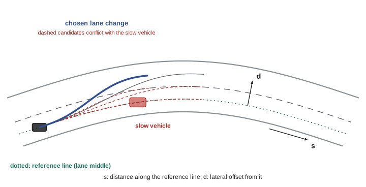
Roads curve, so planning in global x and y coordinates is awkward. Frenet coordinates describe position by \( s \), the distance along a reference line such as the lane centre, and \( d \), the lateral offset from it. A lane change becomes a smooth change in \( d \) while \( s \) increases. A common approach samples many candidate trajectories: for several end times and end offsets, it fits polynomials, typically quintic in \( d \) and quartic in \( s \), that minimize jerk, converts them to global coordinates, checks them against curvature and acceleration limits and against predicted obstacle positions, and picks the lowest-cost survivor. Lattice planners precompute a set of motion primitives on a road-aligned grid and search over them. Optimization-based planners solve directly for a smooth trajectory subject to constraints.
Worked problem
Minimum-jerk lane change
A lateral move of \( d_f = 3.6 \) m over \( T = 4 \) s, starting and ending with zero lateral velocity and acceleration, follows the quintic \( d(t) = d_f(10\tau^3 - 15\tau^4 + 6\tau^5) \) with \( \tau = t/T \). What is the peak lateral acceleration?
Show solution
- Second derivative: \( \ddot{d} = \frac{d_f}{T^2}(60\tau - 180\tau^2 + 120\tau^3) \).
- The bracket peaks at \( \tau = 0.5 - \sqrt{3}/6 \approx 0.211 \), where it equals about 5.77.
- Peak: \( 3.6/16 \times 5.77 \approx 1.30 \) m/s\(^2\).
Answer: About 1.3 m/s², comfortable for passengers. Halving the time to 2 s would quadruple it to 5.2 m/s², which is uncomfortable and too much for winter roads.
Path tracking: pure pursuit and Stanley
Given a reference path, a tracking controller computes the steering angle. Pure pursuit picks a look-ahead point on the path a distance \( l_d \) ahead and steers along the circular arc that would reach it. With \( \alpha \) the angle between the vehicle heading and the line to the look-ahead point, the bicycle geometry gives:
A longer look-ahead gives smoother but lazier tracking that cuts corners; a shorter one tracks tightly but can oscillate. Look-ahead is usually scaled with speed. The Stanley controller, used by Stanford's vehicle in the 2005 DARPA Grand Challenge, references the front axle and combines heading error \( \psi_e \) with cross-track error \( e \): \( \delta = \psi_e + \arctan(k e / v) \). Both are geometric controllers, simple and robust, and both ignore dynamics, so production systems often add feed-forward from path curvature and use them alongside or inside model predictive control.
# Pure pursuit tracking a straight lane after starting 1.5 m off to the side
import numpy as np
L, v, dt = 2.8, 10.0, 0.02
x, y, th = 0.0, 1.5, 0.0          # start 1.5 m left of the path y = 0
for ld in (5.0, 15.0):            # short and long look-ahead
    x, y, th = 0.0, 1.5, 0.0
    ys = []
    for _ in range(int(8 / dt)):
        gx, gy = x + ld, 0.0      # look-ahead point on the line (approximate)
        alpha = np.arctan2(gy - y, gx - x) - th
        delta = np.arctan2(2 * L * np.sin(alpha), ld)
        delta = np.clip(delta, -0.5, 0.5)
        x += v * np.cos(th) * dt; y += v * np.sin(th) * dt
        th += v / L * np.tan(delta) * dt
        ys.append(y)
    ys = np.array(ys)
    settle = np.argmax(np.abs(ys) < 0.1) * dt
print(f"look-ahead {ld:4.1f} m: overshoot {max(0, -ys.min()):.2f} m, within 0.1 m after {settle:.2f} s")look-ahead 5.0 m: overshoot 0.07 m, within 0.1 m after 0.98 s look-ahead 15.0 m: overshoot 0.07 m, within 0.1 m after 2.96 s
Model predictive control
Model predictive control, MPC, from ROB-310, is the workhorse of advanced vehicle control. At each control step it solves an optimization over a short horizon, typically 1 to 3 seconds, finding the sequence of steering and acceleration inputs that best tracks the reference while respecting limits on steering angle and rate, acceleration, jerk and tire friction, then applies the first input and repeats. MPC handles constraints explicitly, anticipates upcoming curvature and can use a dynamic tire model. Its cost is computation: a nonlinear MPC must solve reliably within tens of milliseconds, every cycle, with a fallback if the solver fails. Longitudinal control, speed tracking and following, is often handled by a separate controller such as adaptive cruise control logic or a longitudinal MPC.
Stopping distance, time to collision and safe following distance
Every planner relies on a few safety quantities. The stopping distance is the distance travelled during the reaction or system latency time \( t_r \) plus the braking distance \( v^2/(2a) \). Time to collision, TTC, is the gap to a lead vehicle divided by the closing speed, assuming both keep their speeds; values below about 2 to 3 s commonly trigger warnings and below about 1.5 s emergency braking. The responsibility-sensitive safety model, RSS, proposed by Mobileye researchers in 2017, formalizes a safe longitudinal distance: the following vehicle must be able to stop without collision even if the lead vehicle brakes as hard as possible, given the follower's response time and its guaranteed braking.
# Stopping distance, time to collision and RSS safe distance on dry and snowy roads
import numpy as np
def stopping(v, tr, a):
    return v * tr + v**2 / (2 * a)
def rss(vr, vf, rho, amax, bmin, bmax):
    d = vr * rho + 0.5 * amax * rho**2 + (vr + rho * amax)**2 / (2 * bmin) - vf**2 / (2 * bmax)
    return max(d, 0.0)
v = 100 / 3.6                                  # 100 km/h in m/s
for surface, mu in (("dry", 0.8), ("snow", 0.3)):
    a = mu * 9.81 * 0.9                        # usable braking
    print(f"{surface:5s}: stop from 100 km/h with 0.5 s latency = {stopping(v, 0.5, a):6.1f} m;"
          f" RSS gap (same speeds) = {rss(v, v, 0.5, 2.0, 0.7*a, a):6.1f} m")
gap, v_ego, v_lead = 40.0, v, 60 / 3.6
ttc = gap / (v_ego - v_lead)
print(f"TTC closing on a 60 km/h car 40 m ahead: {ttc:.2f} s")dry : stop from 100 km/h with 0.5 s latency = 68.5 m; RSS gap (same speeds) = 43.3 m snow : stop from 100 km/h with 0.5 s latency = 159.5 m; RSS gap (same speeds) = 91.8 m TTC closing on a 60 km/h car 40 m ahead: 3.60 s
Worked problem
Time to collision
An automated car at 90 km/h approaches a car travelling at 54 km/h, 50 m ahead. What is the TTC, and how hard must the car brake, after a 0.3 s latency, to avoid collision?
Show solution
- Speeds: 25 m/s and 15 m/s, closing at 10 m/s.
- TTC \( = 50/10 = 5.0 \) s.
- During 0.3 s latency the gap shrinks by 3 m to 47 m.
- To shed the 10 m/s closing speed within 47 m: \( a = 10^2/(2 \times 47) \approx 1.06 \) m/s\(^2\).
Answer: TTC is 5 s; gentle braking of about 1.1 m/s² suffices, provided the lead car keeps its speed.
# A minimal ROS 2 node that turns a pure pursuit steering command into an Ackermann message
import math
import rclpy
from rclpy.node import Node
from ackermann_msgs.msg import AckermannDriveStamped
from nav_msgs.msg import Odometry

class PurePursuitNode(Node):
    def __init__(self):
        super().__init__('pure_pursuit')
        self.declare_parameter('wheelbase', 2.8)
        self.declare_parameter('lookahead_gain', 0.8)   # look-ahead = gain * speed + 3 m
        self.pub = self.create_publisher(AckermannDriveStamped, '/vehicle/cmd', 10)
        self.create_subscription(Odometry, '/localization/odom', self.on_odom, 10)

    def on_odom(self, msg):
        v = msg.twist.twist.linear.x
        ld = self.get_parameter('lookahead_gain').value * v + 3.0
        alpha = self.angle_to_lookahead_point(msg, ld)     # from the planned path
        L = self.get_parameter('wheelbase').value
        cmd = AckermannDriveStamped()
        cmd.drive.steering_angle = math.atan2(2 * L * math.sin(alpha), ld)
        cmd.drive.speed = self.target_speed()
        self.pub.publish(cmd)

rclpy.init(); rclpy.spin(PurePursuitNode())
In a real stack, the tracking controller is one node among many, subscribing to the localization estimate and planned trajectory and publishing actuator commands at a fixed rate. Parameters such as wheelbase and look-ahead gain are declared so that they can be tuned per vehicle without recompiling, and a watchdog elsewhere checks that commands keep arriving; if they stop, the vehicle brakes to a stop.
Putting the layers together
A typical automated driving stack runs the behaviour planner at a few hertz, the motion planner at 10 to 20 Hz and the tracking controller at 50 to 100 Hz, with actuator loops faster still. Each layer has checks: the motion planner rejects trajectories exceeding friction limits estimated for the current surface, the controller monitors tracking error, and an independent safety monitor can override the stack with a minimal risk manoeuvre if limits are violated. Winter conditions tighten every limit, which is why a vehicle certified for a dry-weather operational design domain must recognize snow and either adapt or exit its ODD.
Common mistakes
MistakeUsing the kinematic model at high lateral acceleration.
InsteadAbove roughly 0.4 g, or much less on snow, tires slip; use a dynamic model and friction limits.
MistakeFixed look-ahead at all speeds in pure pursuit.
InsteadScale look-ahead with speed to balance stability and tracking.
MistakePlanning only in global coordinates on curved roads.
InsteadFrenet coordinates make lane-relative planning natural.
MistakeIgnoring system latency in stopping distance.
InsteadInclude sensing, compute and actuation delay in the reaction term.
MistakeAssuming the same friction year round.
InsteadEstimate road friction and adapt speed and gaps for snow and ice.
Summary and key terms
- The kinematic bicycle model relates steering to turning radius \( R = L/\tan\delta \) and holds when tires do not slip.
- Lateral acceleration \( v^2/R \) must stay within available friction, which is low on snow and ice.
- Frenet coordinates and sampling or lattice planners generate smooth, lane-relative trajectories.
- Pure pursuit and Stanley are simple geometric trackers; MPC handles constraints and dynamics.
- Stopping distance, TTC and RSS safe distance quantify longitudinal safety margins.
- Layers run at different rates with independent checks and a fallback manoeuvre.
- Bicycle model
- A planar vehicle model merging each axle into a single wheel.
- Wheelbase
- Distance between front and rear axles.
- Slip angle
- Angle between a tire's heading and its direction of travel.
- Frenet coordinates
- Position expressed as distance along and offset from a reference line.
- Lattice planner
- A planner searching precomputed motion primitives on a road-aligned grid.
- Pure pursuit
- A tracker steering toward a look-ahead point on the path.
- Stanley controller
- A tracker combining heading error and cross-track error at the front axle.
- MPC
- Model predictive control, repeated constrained optimization over a moving horizon.
- TTC
- Time to collision: gap divided by closing speed.
- RSS
- Responsibility-sensitive safety, a formal model of safe distances.
Practice problems
Work each problem on paper first, then reveal the answer to check.
Wheelbase 3 m, steering 6 degrees: turning radius?
Show answer
About 28.5 m.
At 15 m/s on a 50 m radius, lateral acceleration?
Show answer
4.5 m/s².
Maximum lateral acceleration on ice with friction 0.1?
Show answer
About 1 m/s².
What does \( d \) represent in Frenet coordinates?
Show answer
Lateral offset from the reference line.
Effect of a longer pure pursuit look-ahead?
Show answer
Smoother, slower convergence and more corner cutting.
Stopping distance at 20 m/s, 0.5 s latency, 6 m/s² braking?
Show answer
10 + 33.3 = 43.3 m.
Gap 30 m, closing at 6 m/s: TTC?
Show answer
5 s.
What does RSS assume about the lead vehicle?
Show answer
It may brake as hard as possible.
Why does MPC need a fallback?
Show answer
The solver may fail to converge in time.
Typical rate of a tracking controller?
Show answer
About 50 to 100 Hz.
Lesson quiz · 5 questions
Score 60% or more to complete this lesson.
Create a free account to save your progress, take quizzes and earn a certificate.