
CINE-340 · Lesson 3 of 12 · 32 min
Power distribution, generators and tie-ins
Lesson 2 explained how electricity behaves. This lesson follows the power from its source to the light. On most location shoots that source is a portable generator; on stages it is house power through studio distribution; occasionally it is a tie-in to a building's electrical service. From the source, feeder cable carries power to distribution boxes, which split it into smaller circuits for individual fixtures. Every link in that chain must be correctly sized, protected and placed. A generator in the wrong place can poison a crew with carbon monoxide; an unbalanced load can overheat a neutral; a feeder run that is too long can drop the voltage so far that fixtures misbehave; and an improper tie-in can electrocute someone or set a building on fire. This lesson covers the distribution chain, generator selection and placement, load balancing, voltage drop, fuel and run time, and the rules around tie-ins.
The distribution chain
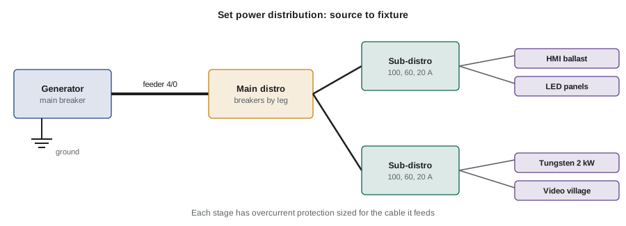
A typical set power system has several stages.
- Source: a generator, studio house power or a tie-in to a building service.
- Main disconnect and overcurrent protection at the source, so the whole system can be switched off and protected.
- Feeder cable: heavy single-conductor cable, often 4/0 or 2/0 copper, carrying three hot legs, a neutral and a ground from the source to the set.
- Main distribution box, sometimes called a spider box splitter, "lunch box" for small circuits or a "company switch" when built into a building.
- Sub-distribution: smaller distribution boxes with breakers that feed 100 A, 60 A or 20 A circuits through stage pin, bates, twist-lock or Edison connectors.
- Branch circuits: extension cables (stingers) and fixtures.
- Dimmers and DMX control may sit between the distribution and the fixtures, letting the gaffer adjust levels from a console.
Each stage has overcurrent protection sized for the cable it feeds. As a rule, a smaller cable must never be connected downstream of a breaker rated for a larger cable unless there is protection sized for the smaller cable.
Generators for film
Film generators are designed for the job: quiet enough for sound recording, with stable voltage and frequency, sound-attenuated enclosures, built-in distribution panels and electronic governors that cope with electronic loads.
- Sizes range from small portable inverter generators of 2 to 7 kW for small shoots to tow-behind and truck-mounted units of 100 to 1,400 kW for features and large commercials.
- Most produce 120/208 V three-phase, with panels for Cam-Lok feeder connections and receptacles.
- Sound-blimped "movie" generators are designed to be quiet at a distance; sound crews still prefer them as far away as practical.
- Many productions now add battery energy storage systems or hybrid generator-battery units, which reduce fuel, noise and emissions and can run small loads silently.
- Generators are operated by trained crew, often a dedicated generator operator, who monitors load, voltage, frequency, fuel and temperature.
Generator placement and carbon monoxide
Where a generator sits is a safety decision as well as a sound and logistics decision.
- Carbon monoxide (CO) from exhaust is colourless, odourless and deadly. Never run a generator indoors, in a garage, under a tent, near open windows, doors or air intakes, or in a low area where exhaust can pool.
- Place generators downwind of the set, base camp and dressing rooms where possible, with the exhaust pointed away from people.
- Keep fuel storage, refuelling areas and the generator away from ignition sources, with fire extinguishers nearby and spill kits ready (US Bulletin 13 covers combustible and flammable fuels).
- Keep generators on stable, level ground, chocked and secured, with barriers to keep the public away.
- Ground generators as required by code and manufacturer instructions; the US Bulletin 23E covers generator grounding.
- Keep cables from the generator out of traffic and walkways, using cable ramps where they must cross.
- Consider noise: hearing protection near large units, and placement that keeps noise away from neighbours (Lesson 8 covers noise dose).
Worked problem
How long will the fuel last?
A diesel generator running a 48 kW load uses about 0.30 L of fuel per kWh at that load. The tank holds 400 L. How long can it run, and how much fuel is used on a 12-hour day?
Show solution
- Fuel use per hour: 48 kW × 0.30 L/kWh = 14.4 L/h. Run time on a full tank: 400 ÷ 14.4 ≈ 27.8 h. On a 12-hour day: 14.4 × 12 ≈ 173 L.
- Generators use more fuel per kWh at light loads, so a lightly loaded large generator wastes fuel; right-sizing or adding battery storage improves efficiency.
Answer: About 28 hours on a full tank and about 173 L for a 12-hour day. The figures are illustrative; check the manufacturer's fuel curve, and plan refuelling with the fuel supplier so that it happens safely and away from the set.
Balancing the load across phases
On a three-phase system, the gaffer aims to spread single-phase loads evenly across the three legs. A badly unbalanced system overloads one leg while others sit idle, raises neutral current and can make a generator run poorly.
- Each fixture or circuit is assigned to a leg, often colour-coded on the distribution (in North America, commonly red, black and blue for legs, white for neutral and green for ground on film feeder).
- Electricians keep a running log or plot showing which fixtures are on which leg and the current on each.
- Clamp meters measure actual current on each leg and the neutral, since real loads differ from nameplate ratings.
- When fixtures are added or switched off during the day, the balance is checked again.
For resistive loads, the current in the neutral of a three-phase system depends on the imbalance between the legs:
When the three currents are equal, the neutral current is zero. Harmonics from electronic loads add extra neutral current on top of this, as Lesson 2 explained.
Worked problem
Balancing a three-phase generator
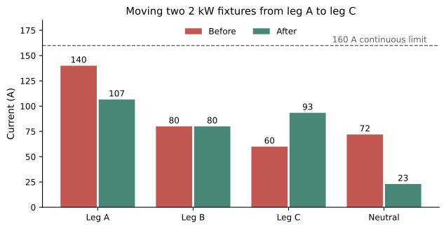
A gaffer's plot shows leg A at 140 A, leg B at 80 A and leg C at 60 A of mostly tungsten load. What is the neutral current? If two 2 kW tungsten fixtures (about 16.7 A each) are moved from leg A to leg C, what are the new leg currents and neutral current?
Show solution
- Before: \( I_N = \sqrt{140^2 + 80^2 + 60^2 - 140 \times 80 - 80 \times 60 - 60 \times 140} \).
- \( = \sqrt{19600 + 6400 + 3600 - 11200 - 4800 - 8400} = \sqrt{5200} \approx 72 \) A.
- After moving 33.4 A: A ≈ 106.6 A, B = 80 A, C ≈ 93.4 A.
- \( I_N = \sqrt{106.6^2 + 80^2 + 93.4^2 - 106.6 \times 80 - 80 \times 93.4 - 93.4 \times 106.6} \approx \sqrt{531} \approx 23 \) A.
Answer: The neutral current falls from about 72 A to about 23 A, and the highest leg falls from 140 A to about 107 A. Moving a few fixtures makes the system cooler, safer and better for the generator.
Cable sizing and voltage drop
Feeder cable must carry the load without overheating, and long runs must not drop the voltage too far.
- Ampacity is the current a cable can carry continuously without exceeding its temperature rating. It depends on conductor size, insulation type, ambient temperature and whether the cable is in free air, bundled or covered. Film distribution uses tables from the electrical code and cable manufacturer; 4/0 single-conductor portable cable, for example, is commonly rated in the region of 400 A in free air, but the exact value must come from the code and manufacturer tables.
- Voltage drop occurs because even copper has resistance. Over long runs at high current, fixtures receive less voltage. Tungsten lamps shift warmer and dimmer; electronic ballasts may shut down or behave erratically.
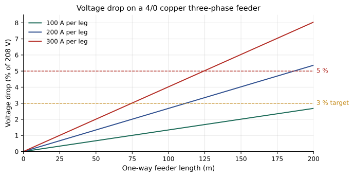
- A common design target is to keep voltage drop below about 3 to 5 % at the fixture.
For a balanced three-phase feeder, the line-to-line voltage drop is approximately:
Here \( I \) is the current per leg, \( R_{\text{per length}} \) the resistance of one conductor per unit length and \( L \) the one-way length of the run.
Worked problem
Voltage drop on a long feeder run
A 120/208 V feeder of 4/0 copper (resistance about 0.161 Ω per km per conductor) runs 100 m from a generator to set, carrying 200 A per leg. What is the voltage drop, and as a percentage of 208 V?
Show solution
- Resistance of 100 m of one conductor: 0.161 × 0.1 = 0.0161 Ω. Voltage drop: \( \sqrt{3} \times 200 \times 0.0161 \approx 5.6 \) V.
- As a percentage: 5.6 ÷ 208 ≈ 2.7 %. Doubling the run to 200 m doubles the drop to about 5.4 %.
Answer: The drop is under 3 % for the shorter run but approaches 5 % if the run doubles. Long runs need a larger cable, parallel runs, a closer generator or a lower load. Resistance also rises as cable heats up, so real drops are a little higher.
Sizing distribution and generators
The gaffer sizes the generator and distribution from the lighting plan, adding margin for changes on the day.
- List every fixture and its power, including practicals, video village, chargers and support loads.
- Convert to current per leg, accounting for power factor of electronic loads.
- Apply the continuous load guideline of about 80 % of the rating of breakers, cables and generators.
- Add a margin for creative changes; DPs often ask for "one more light".
- Choose a generator whose rated output, not peak output, covers the load, and consider electronic load compatibility.
| Connector | Typical rating | Common use |
|---|---|---|
| Cam-Lok (16 series) | Up to about 400 A single conductor | Feeder from generator to distribution |
| Bates (stage pin) 100 A | 100 A, 120 V | Large tungsten and HMI ballasts |
| Bates 60 A | 60 A, 120 V | Medium fixtures, sub-distribution |
| Bates 20 A | 20 A, 120 V | Individual fixtures |
| Twist-lock (for example L21-30) | 30 A three-phase | Lunch boxes, dimmer packs |
| Edison (NEMA 5-15/5-20) | 15 to 20 A, 120 V | Small fixtures, chargers, practicals |
| Socapex and multicore | Varies | Multiple dimmed circuits in one cable |
Worked problem
Sizing a generator
A lighting package includes 2 × 18 kW HMI ballasts (power-factor corrected, about 19 kVA each), 6 × 1.2 kW LED panels (about 1.3 kVA each), video village and chargers at 4 kVA and practicals at 3 kW. Assuming a power factor near 1 for the practicals, what is the approximate total, and what generator size is appropriate with 80 % continuous loading?
Show solution
- HMIs: 2 × 19 = 38 kVA. LEDs: 6 × 1.3 = 7.8 kVA. Village and chargers: 4 kVA. Practicals: 3 kVA.
- Total ≈ 52.8 kVA.
- For 80 % continuous loading, rated capacity ≥ 52.8 ÷ 0.8 = 66 kVA.
- Add margin for changes: a 70 to 100 kVA (roughly 56 to 80 kW) film generator would be a common choice, depending on what is available.
Answer: About 53 kVA of load, so a generator of at least 66 kVA, and in practice 70 to 100 kVA, with distribution sized to match. Figures are illustrative; real ballasts and drivers vary.
House power and studio distribution
On sound stages, power comes from studio distribution with fixed outlets and panels designed for film lighting. Studios have their own rules about who may connect and which outlets to use. In ordinary buildings on location, using wall outlets is limited to small loads on circuits whose capacity and wiring are known. Plugging large fixtures into domestic outlets risks overloading old wiring that may already be shared with other loads.
Tie-ins: connecting to a building's service
A tie-in connects film distribution directly to a building's electrical service, usually at a panel or disconnect, instead of using a generator. It can save fuel and noise but is among the most hazardous electrical tasks on a production.
- Tie-ins involve working on or near energized conductors with very high available fault current, creating serious shock and arc flash risk.
- Only qualified and, where required, licensed electricians may perform tie-ins, using proper equipment, protective gear and procedures.
- The building owner's permission and an assessment of the service capacity are needed.
- Many jurisdictions require permits or inspections; many studios and productions prohibit tie-ins except by approved electrical contractors.
In Canada, connecting to a building's electrical service is electrical installation work under the Canadian Electrical Code and provincial regulations. It generally requires a licensed electrician or electrical contractor and, depending on the province, a permit or notification to the electrical safety authority. Provincial OHS rules require procedures for working near energized equipment, and CSA Z462 guides arc flash risk assessment and protective equipment.
Common mistakes
MistakeRunning a generator near open doors, intakes or in an enclosed space.
InsteadPlace it outdoors, downwind and away from openings, and monitor for carbon monoxide.
MistakeLoading one leg heavily while others stay light.
InsteadPlot and measure each leg and move fixtures to balance the load.
MistakeIgnoring voltage drop on long feeder runs.
InsteadCalculate drop, and use larger or parallel cable or move the generator closer.
MistakeSizing a generator for its peak rating.
InsteadUse the continuous rating with about 20 % margin for loads that run for hours.
MistakeLetting an unqualified person do a tie-in.
InsteadTie-ins are for qualified, licensed electricians with permits and arc flash protection.
Summary and key terms
- Power flows from source to feeder, distribution boxes, branch circuits and fixtures, with protection at each stage.
- Film generators are quiet, stable and sized from the lighting plan with continuous-load margins.
- Generators must be placed outdoors, downwind and away from openings to prevent carbon monoxide poisoning.
- Balancing loads across three legs reduces neutral current and stress on the generator.
- Voltage drop rises with current and length; long runs need larger or parallel cable.
- Fuel use and run time are planned with refuelling done safely away from the set.
- Tie-ins are hazardous, regulated work for qualified, licensed electricians only.
- Feeder cable
- Heavy cable carrying power from the source to distribution.
- Distribution box
- A box with breakers that splits feeder power into smaller circuits.
- Cam-Lok
- A single-pole connector widely used on film feeder cable.
- Bates connector
- A stage pin connector used on film power circuits.
- Load balancing
- Spreading single-phase loads evenly across three phases.
- Voltage drop
- The loss of voltage along a cable due to its resistance.
- Ampacity
- The current a conductor can carry continuously without overheating.
- Tie-in
- A connection of film distribution to a building's electrical service.
- Carbon monoxide
- A colourless, odourless toxic gas in engine exhaust.
- Generator operator
- The crew member who runs and monitors the generator.
Practice problems
Work each problem on paper first, then reveal the answer to check.
Why place a generator downwind?
Show answer
To keep exhaust and carbon monoxide away from people.
Neutral current when legs are 100, 100 and 100 A?
Show answer
Zero for resistive loads.
Voltage drop percent target for feeder runs?
Show answer
Below about 3 to 5 %.
How does doubling run length change voltage drop?
Show answer
It doubles it.
Fuel use for 30 kW at 0.30 L/kWh?
Show answer
About 9 L per hour.
Minimum generator rating for a 40 kVA continuous load at 80 %?
Show answer
50 kVA.
Who may perform a tie-in?
Show answer
Only qualified, licensed electricians, with permits where required.
Why not leave loaded feeder cable coiled?
Show answer
It cannot shed heat and can overheat.
What tool measures actual current on each leg?
Show answer
A clamp meter.
What does a battery energy storage system add to a generator?
Show answer
Lower fuel use, noise and emissions, and silent running for small loads.
Lesson quiz · 5 questions
Score 60% or more to complete this lesson.
Create a free account to save your progress, take quizzes and earn a certificate.