
ROB-220 · Lesson 3 of 12 · 29 min
Inertial sensors: accelerometers, gyroscopes and magnetometers
An inertial measurement unit, or IMU, is the robot's inner ear. It measures acceleration and rotation rate without reference to anything outside the robot, which makes it invaluable for balancing, stabilizing drones, estimating orientation and bridging gaps when cameras or satellite signals drop out. Modern MEMS IMUs cost a few dollars, fit in a few cubic millimetres and appear in almost every mobile robot, phone and drone. They are also among the most misunderstood sensors, because their outputs must be integrated to give orientation, velocity and position, and integration turns small errors into large ones. This lesson explains what each inertial sensor actually measures, how its errors behave and what that means for a robot.
Accelerometers measure specific force
A MEMS accelerometer contains a tiny proof mass suspended on springs etched in silicon. When the case accelerates, the mass lags behind, and the deflection is measured as a change in capacitance between interleaved comb fingers. Three such structures at right angles make a three-axis accelerometer. The subtle point is what the deflection represents. The sensor cannot distinguish the force of gravity from the force needed to accelerate, so it measures specific force: the non-gravitational force per unit mass.
Here \( \mathbf{a} \) is the true acceleration and \( \mathbf{g} \) the gravity vector, pointing down with magnitude about 9.81 m/s². An accelerometer lying still on a table has \( \mathbf{a} = 0 \) and therefore reads \( -\mathbf{g} \): 1 g upward, the reaction of the table. In free fall it reads zero. This is a blessing and a curse. When the robot is still or moving at constant velocity, the accelerometer measures the direction of gravity and so gives roll and pitch, the tilt of the robot. When the robot accelerates, the reading mixes tilt and motion, and the two cannot be separated from the accelerometer alone.
Worked problem
Tilt from a stationary accelerometer
A stationary robot's accelerometer reads \( (f_x, f_y, f_z) = (-1.70, 0.85, 9.62) \) m/s². Find the roll and pitch angles using the formulas above.
Show solution
- Magnitude: \( \sqrt{1.70^2 + 0.85^2 + 9.62^2} = 9.81 \) m/s², consistent with gravity only.
- Roll: \( \phi = \operatorname{atan2}(0.85, 9.62) = 5.0° \).
- Pitch: \( \theta = \operatorname{atan2}(1.70, \sqrt{0.85^2 + 9.62^2}) = \operatorname{atan2}(1.70, 9.66) = 10.0° \).
Answer: Roll about 5° and pitch about 10°. Checking that the magnitude is close to 9.81 m/s² is a useful test that the robot really is unaccelerated before trusting the tilt.
Accelerometers cannot measure yaw, the heading about the vertical axis, because rotating about the gravity vector does not change the gravity reading. Heading needs a gyroscope, a magnetometer or an external reference.
Gyroscopes measure angular rate
A MEMS gyroscope is a vibrating structure. A mass is driven to oscillate along one axis; when the sensor rotates, the Coriolis effect pushes the moving mass sideways with a force proportional to the rotation rate, and that tiny sideways motion is detected capacitively. The output is angular velocity, typically in degrees per second, about each of three axes. Unlike an accelerometer, a gyroscope is not fooled by linear acceleration, so it tracks fast rotations cleanly. To get an angle, however, the rate must be integrated over time.
Any constant bias b in the rate becomes an angle error that grows linearly with time, \( b\,t \). A consumer gyroscope with a bias of 0.5 °/s that is not removed accumulates 30° of heading error in a minute. Even after the start-up bias is measured and subtracted, the bias wanders slowly with temperature and time, and random noise integrates into an angle random walk whose spread grows with the square root of time. This is why gyroscope angles drift and why every practical system corrects them with something else: the accelerometer for roll and pitch, and a magnetometer, vision or satellite heading for yaw.
Worked problem
Heading drift from gyroscope bias
A ground robot estimates heading by integrating a gyroscope whose residual bias, after start-up calibration, is 0.02 °/s. How large is the heading error after 5 minutes? If the robot then drives 50 m straight, how far sideways is its estimated position from the truth?
Show solution
- Heading error: \( 0.02 \times 300 = 6° \).
- Lateral error over 50 m: \( 50 \sin 6° = 50 \times 0.1045 = 5.2 \) m.
- The position error grows with both time and distance travelled.
Answer: About 6° of heading error, which turns into roughly 5 m of sideways error over a 50 m drive. Small rate biases become large position errors.
Magnetometers and heading
A magnetometer measures the local magnetic field in three axes, usually with magnetoresistive or Hall-effect elements. Its horizontal component points towards magnetic north, which gives an absolute heading reference that does not drift. In practice it is the least trustworthy of the three IMU sensors on a robot. Motors, magnets and steel frames distort the field (hard-iron errors from permanent magnets add an offset; soft-iron errors from ferrous materials distort the shape), currents in nearby wires create fields that change with motor load, and indoors the field is bent by reinforcing steel. Magnetic north also differs from true north by the declination, which varies with location and time. Most robots therefore use magnetometers only outdoors, calibrate them by rotating the robot through many orientations, mount them away from motors and power cables, and give them low weight in the fusion filter.
The field's magnetic declination is published by national geological agencies and in the World Magnetic Model. Across North America it ranges from roughly 20° west in eastern Canada to around 15° east in parts of the western United States, enough to send a robot badly astray if it is ignored.
IMU error sources
Datasheets describe IMU errors with a standard set of terms. Knowing them lets you compare a $5 consumer part with a $5,000 tactical-grade unit and decide what your robot really needs.
| Error | What it is | Effect after integration |
|---|---|---|
| Bias (offset) | Nonzero output with zero input | Gyro: angle error grows ∝ t. Accel: position error grows ∝ t² |
| Bias instability | Slow wander of the bias | Limits how long a calibration stays valid |
| Scale-factor error | Gain slightly wrong, e.g. 0.5 % | Error proportional to the motion itself |
| Misalignment / cross-axis | Axes not exactly orthogonal | Motion on one axis leaks into another |
| White noise (random walk) | Fast random fluctuations | Angle or velocity random walk ∝ √t |
| Temperature sensitivity | Bias and scale change with heat | Drift as the robot warms up |
| Vibration rectification | Vibration produces a false average | Bias appears when motors run |
The double integration needed to get position from an accelerometer is especially unforgiving. A constant accelerometer bias of b produces a position error of \( \tfrac{1}{2}b t^2 \). A tilt error is equivalent to an accelerometer bias, because a robot that thinks it is level when it is tilted by a small angle \( \delta \) misattributes \( g\sin\delta \) of gravity as horizontal acceleration.
Worked problem
Why inertial-only position drifts
An IMU-only estimate has an uncorrected horizontal accelerometer bias of 0.01 m/s² (about 1 mg). How far off is the position after 10 s, 60 s and 5 minutes? What tilt error gives the same bias?
Show solution
- \( e = \tfrac{1}{2} b t^2 \). At 10 s: \( 0.5 \times 0.01 \times 100 = 0.5 \) m.
- At 60 s: \( 0.5 \times 0.01 \times 3600 = 18 \) m. At 300 s: \( 0.5 \times 0.01 \times 90\,000 = 450 \) m.
- Equivalent tilt: \( \sin\delta = 0.01/9.81 \), so \( \delta \approx 0.058° \).
Answer: Half a metre after 10 s, 18 m after a minute and 450 m after 5 minutes. A tilt error of only 0.06° causes the same bias, which is why consumer IMUs alone cannot hold position for more than a few seconds.
Allan variance: characterizing noise and drift
How do you measure bias instability and random walk? The standard tool is the Allan variance. Record the stationary sensor for a long time, perhaps several hours, then split the record into clusters of length \( \tau \), average each cluster, and compute half the mean squared difference between consecutive cluster averages. Repeating for many values of \( \tau \) and plotting the square root, the Allan deviation, on log-log axes produces a characteristic curve. At short averaging times white noise dominates and the curve falls with a slope of −½; the value at \( \tau = 1 \) s on that line gives the angle (or velocity) random walk. The curve flattens at its minimum, which defines the bias instability, the best stability averaging can achieve. At long times slow drifts make the curve rise again.
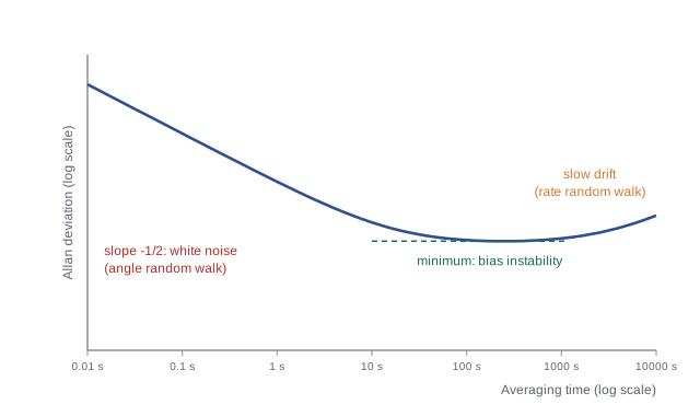
The code below simulates a gyroscope with white noise and a slowly wandering bias and computes its Allan deviation at a few averaging times. You will meet this analysis again when tuning the noise parameters of the Kalman filters in ROB-310.
import numpy as np
rng = np.random.default_rng(7)
fs, T = 100, 3600                        # 100 Hz for one hour
n = fs * T
white = rng.normal(0, 0.05, n)           # deg/s white noise
walk = np.cumsum(rng.normal(0, 2e-5, n)) # slowly wandering bias, deg/s
y = 0.3 + white + walk                   # constant bias 0.3 deg/s
def adev(y, m):
    k = len(y) // m
    means = y[:k*m].reshape(k, m).mean(axis=1)
    return np.sqrt(0.5 * np.mean(np.diff(means)**2))
for tau in (0.1, 1, 10, 100, 1000):
print(f"tau = {tau:7.1f} s Allan deviation = {adev(y, int(tau*fs)):.5f} deg/s")tau = 0.1 s Allan deviation = 0.01562 deg/s tau = 1.0 s Allan deviation = 0.00507 deg/s tau = 10.0 s Allan deviation = 0.00161 deg/s tau = 100.0 s Allan deviation = 0.00121 deg/s tau = 1000.0 s Allan deviation = 0.00397 deg/s
The constant bias of 0.3 °/s does not appear in the Allan deviation at all, because it cancels in the differences. The Allan analysis describes how the bias changes, not its starting value, which still has to be measured at start-up.
Choosing an IMU and mounting it well
IMUs are loosely graded by gyroscope bias instability: consumer parts at roughly 1 to 10 °/h (and much worse over temperature), industrial parts around 1 °/h, tactical grade around 0.1 to 1 °/h and navigation grade at 0.01 °/h or better, with prices rising by orders of magnitude at each step. A legged robot or drone that fuses the IMU with other sensors many times a second is usually well served by a good industrial MEMS part; a survey vehicle that must ride through a long tunnel without satellite signals may need tactical grade.
Mounting matters as much as the part number. Place the IMU near the robot's centre of rotation to reduce centripetal accelerations, isolate it from motor vibration with a compliant mount whose resonance lies well below the vibration frequencies, avoid placing it beside high-current wiring, and record its exact position and orientation in the robot's transform tree. A rigid but noisy mount can produce vibration rectification, a false bias that appears only when the motors spin, which is maddening to debug in the field.
Common mistakes
MistakeExpecting an accelerometer to read zero when the robot is still.
InsteadA stationary accelerometer reads 1 g upward, the reaction to gravity; it reads zero only in free fall.
MistakeComputing tilt from the accelerometer while the robot is accelerating.
InsteadTilt from gravity is valid only when acceleration is small; otherwise fuse with the gyroscope.
MistakeIntegrating a gyroscope for heading without removing the start-up bias.
InsteadMeasure and subtract the bias while stationary, and still expect drift that needs an external correction.
MistakeTrusting a magnetometer next to motors and steel.
InsteadCalibrate for hard- and soft-iron errors, mount away from currents and magnets, and correct for declination.
MistakeDouble-integrating accelerometer data for long-term position.
InsteadBias and tilt errors grow quadratically; inertial position needs frequent correction from other sensors.
Summary and key terms
- Accelerometers measure specific force, \( \mathbf{a} - \mathbf{g} \), so a still sensor reads 1 g upward.
- When unaccelerated, the accelerometer gives roll and pitch, but never yaw.
- Gyroscopes measure angular rate via the Coriolis effect; integrating a bias gives angle error that grows linearly.
- Magnetometers give absolute heading but suffer hard- and soft-iron errors, interference and declination.
- IMU errors include bias, bias instability, scale factor, misalignment, noise, temperature effects and vibration rectification.
- Accelerometer bias produces position error proportional to \( t^2 \); a 0.06° tilt error equals a 1 mg bias.
- The Allan deviation reveals random walk and bias instability and guides filter tuning.
- IMU
- Inertial measurement unit: accelerometers and gyroscopes, often with a magnetometer.
- Specific force
- Non-gravitational force per unit mass, the quantity an accelerometer measures.
- MEMS
- Micro-electro-mechanical systems: tiny machines etched in silicon.
- Coriolis effect
- The sideways force on a moving mass in a rotating frame, used by vibrating gyroscopes.
- Angle random walk
- Angle error from integrated white rate noise, growing with √t.
- Bias instability
- The minimum of the Allan deviation; how stable the bias is.
- Hard-iron error
- Magnetometer offset caused by permanent magnetic fields on the robot.
- Soft-iron error
- Magnetometer distortion caused by nearby ferrous materials.
- Magnetic declination
- The angle between magnetic north and true north at a location.
- Allan deviation
- A measure of sensor stability as a function of averaging time.
Practice problems
Work each problem on paper first, then reveal the answer to check.
What does a three-axis accelerometer read in free fall?
Show answer
Zero on all axes.
A still accelerometer reads (0, 4.9, 8.5) m/s². What is the roll?
Show answer
\( \operatorname{atan2}(4.9, 8.5) \approx 30° \).
Can an accelerometer measure yaw? Why?
Show answer
No; rotating about the gravity vector does not change the gravity reading.
A gyro bias of 0.1 °/s is integrated for 2 minutes. What is the angle error?
Show answer
12°.
A 2 mg accelerometer bias is double-integrated for 30 s. What is the position error?
Show answer
\( b = 0.0196 \) m/s²; \( 0.5 \times 0.0196 \times 900 \approx 8.8 \) m.
What slope does white noise produce on an Allan deviation plot?
Show answer
−½ on log-log axes.
Why does the constant bias not appear in the Allan deviation?
Show answer
It cancels in the differences between consecutive cluster averages.
Name two ways to reduce magnetometer errors on a robot.
Show answer
Mount it away from motors and current-carrying wires; calibrate by rotating through many orientations.
What is vibration rectification?
Show answer
A false average bias produced when vibration interacts with sensor nonlinearity.
Why place an IMU near the robot's centre of rotation?
Show answer
To minimize centripetal and tangential accelerations from rotation that would contaminate the accelerometer.
Lesson quiz · 5 questions
Score 60% or more to complete this lesson.
Create a free account to save your progress, take quizzes and earn a certificate.