
ROB-300 · Lesson 11 of 12 · 37 min
Robust, adaptive and digital control in practice
The controllers of the previous lessons were designed for a model, and they were analysed in continuous time. Real robots differ from their models: payloads change, friction drifts with temperature and wear, gearboxes flex and cables pull. Real controllers run on computers with finite sample rates, delays, jitter and quantized signals, and drive actuators with hard limits. This lesson gathers the practical knowledge that bridges theory and a working robot: how to make controllers robust to model error, how to let them adapt to unknown parameters, how to estimate parameters from data, how to structure motion control as cascaded current, velocity and position loops, and how to implement everything in discrete time without losing the properties designed in continuous time.
Sources of uncertainty
Model error in robots comes from a handful of predictable sources. Payload is the largest variable one: a robot rated for 10 kg may carry anything from nothing to 10 kg, and the payload's inertia and centre of mass change with how it is gripped. Friction varies with temperature (cold grease can double it), speed, load and wear. Link and gearbox stiffness are known only approximately, and cables and hoses add forces that are hard to model. Inertial parameters from CAD omit fasteners, wiring and paint. Finally, unmodelled dynamics, such as motor inductance, sensor filters, delays and structural modes, are deliberately left out of control models but limit the achievable bandwidth. Robust control accepts the uncertainty and designs for its worst case; adaptive control reduces it by learning; identification reduces it in advance.
Robustness through high gain and integral action
The simplest robustness comes from feedback itself. Model error enters computed torque control as a disturbance η (lesson 9), and the error it causes falls in proportion to the feedback gains. Integral action removes the steady part completely. The limit is set by the unmodelled dynamics: gains high enough to suppress large model errors push the loop bandwidth toward resonances and delays, which the stability margins of lesson 5 forbid. A rule of thumb is that feedback can tolerate model errors whose effect is well below the disturbance-rejection capability at the chosen bandwidth, and anything larger needs better modelling or adaptation.
Worked problem
Tracking error caused by model error
A computed torque controller with \( \omega_n \) = 25 rad/s (critical damping) has a 15 % inertia error. During a move with peak acceleration 8 rad/s², the mismatch produces a disturbance acceleration of about \( 0.15 \times 8 = 1.2 \) rad/s². Estimate the resulting peak error, and the error with \( \omega_n \) = 50 rad/s.
Show solution
- For a slowly varying disturbance acceleration η, the error is roughly \( \eta/K_p = \eta/\omega_n^2 \).
- \( \omega_n \) = 25: \( 1.2/625 = 1.9 \times 10^{-3} \) rad.
- \( \omega_n \) = 50: \( 1.2/2500 = 4.8 \times 10^{-4} \) rad.
Answer: About 1.9 mrad at 25 rad/s, falling to 0.48 mrad at 50 rad/s: doubling the bandwidth cuts model-error effects by four. Even so, 50 rad/s must stay inside the limit of about 84 rad/s set by the 252 rad/s resonance of lesson 3's flexible joint, with delay eating into the margin as well, so in practice the bandwidth limit, not the model error, decides how far the gains can go.
Sliding mode and robust control
Sliding mode control makes robustness explicit. Define a sliding variable that combines error and its rate, \( s = \dot{e} + \lambda e \); if s is kept at zero, the error decays as \( e^{-\lambda t} \) regardless of the dynamics. The controller adds a switching term large enough to dominate the worst-case uncertainty:
where \( |\eta|_{\max} \) bounds the model-error acceleration and sat is a saturation function that replaces the ideal discontinuous sign function inside a thin boundary layer of width φ. The pure sign function would guarantee perfect tracking but cause chattering, rapid switching that excites resonances and wears actuators; the boundary layer trades a small residual error, of order \( \phi/\lambda \), for smooth control. Sliding mode is used where uncertainty bounds are known and robustness matters more than smoothness, for example in some legged robots and underwater vehicles. Other robust methods, such as \( H_\infty \) design, shape the closed loop to tolerate uncertainty described in the frequency domain.
Worked problem
Choosing a sliding mode gain
For the joint of the previous example the model-error acceleration can reach 2 rad/s² (heavy payload). Choose λ = 20 s⁻¹, a switching gain k with a 25 % safety factor, and a boundary layer giving a residual error below 1 mrad.
Show solution
- Switching gain: k = 1.25 × 2 = 2.5 rad/s².
- Residual error is of order \( \phi/\lambda \); for 1 mrad, \( \phi \le 0.001 \times 20 = 0.02 \) rad/s.
Answer: λ = 20 s⁻¹, k = 2.5 rad/s² and φ = 0.02 rad/s. Inside the boundary layer the switching term behaves like a high-gain linear term \( k/\phi = 125 \) s⁻², which must still respect the bandwidth limits; if it causes vibration, widen φ.
The disturbance observer
A practical robust technique popular in industrial servo drives is the disturbance observer (DOB). It compares the torque commanded with the torque implied by the measured acceleration and a nominal inertia, and treats the difference as an estimated disturbance:
where Q(s) is a low-pass filter. Subtracting \( \hat{d} \) from the next torque command cancels friction, gravity errors, payload changes and coupling within the filter bandwidth, making the joint behave like the nominal inertia \( \hat{J} \). The outer controller can then be designed for the nominal model. The filter bandwidth sets the trade-off: wider rejects more disturbance but amplifies acceleration noise and erodes stability margins. A DOB essentially gives integral-like disturbance rejection without the overshoot penalty of a large integrator.
Worked problem
Disturbance observer estimate
A joint with nominal inertia \( \hat{J} \) = 1.5 kg·m² is commanded 12 N·m and measured to accelerate at 5.2 rad/s² in steady conditions. What disturbance does the observer estimate, and what might it represent?
Show solution
- Torque implied by the measured motion: \( \hat{J}\ddot{q} = 1.5 \times 5.2 = 7.8 \) N·m.
- Estimated disturbance: \( \hat{d} = 12 - 7.8 = 4.2 \) N·m (after the low-pass filter settles).
Answer: \( \hat{d} \) ≈ 4.2 N·m, the sum of friction, gravity error and any extra inertia. Adding 4.2 N·m to subsequent commands restores the nominal response.
Adaptive control and parameter identification
Adaptive control estimates uncertain parameters while the robot runs and uses the estimates in a model-based controller. It relies on the linear-in-parameters property of lesson 2: \( \mathbf{M}\ddot{\mathbf{q}} + \mathbf{C}\dot{\mathbf{q}} + \mathbf{g} = \mathbf{Y}(\mathbf{q},\dot{\mathbf{q}},\ddot{\mathbf{q}})\boldsymbol{\theta} \). The Slotine–Li adaptive controller, from 1987, combines a computed-torque-like law using the current estimate \( \hat{\boldsymbol{\theta}} \) with an update law \( \dot{\hat{\boldsymbol{\theta}}} = -\boldsymbol{\Gamma}\mathbf{Y}^{\mathsf{T}}\mathbf{s} \), driven by a sliding-like error s and an adaptation gain Γ. A Lyapunov proof, again using the skew-symmetry of \( \dot{\mathbf{M}} - 2\mathbf{C} \), shows that tracking errors converge to zero. Parameter estimates converge to the true values only if the trajectory is persistently exciting, that is, rich enough in motion to reveal every parameter.
Offline identification uses the same structure without real-time adaptation. The robot follows an exciting trajectory, joint torques (from motor currents) and motions are recorded, and the parameter vector is found by least squares, stacking the regressor for every sample: \( \hat{\boldsymbol{\theta}} = (\mathbf{Y}^{\mathsf{T}}\mathbf{Y})^{-1}\mathbf{Y}^{\mathsf{T}}\boldsymbol{\tau} \). Payload identification, a common feature of industrial robots, runs a short test motion after the robot picks up a tool and estimates its mass and centre of mass the same way.
Worked problem
Estimating payload mass at rest
A robot holds its arm horizontal with and without a payload gripped 0.6 m from the shoulder. The shoulder holding torque rises from 13.7 to 25.5 N·m. Estimate the payload mass.
Show solution
- Extra gravity torque: \( 25.5 - 13.7 = 11.8 \) N·m.
- For a payload at 0.6 m with the arm horizontal: \( m_pg \times 0.6 = 11.8 \).
- \( m_p = 11.8/(9.81 \times 0.6) = 2.0 \) kg.
Answer: About 2.0 kg. A single static pose identifies only the product of mass and lever arm in one direction; a second pose or a short motion separates mass from centre-of-mass position and reveals inertia.
import numpy as np
rng = np.random.default_rng(3)
# true single-link parameters: inertia, gravity coefficient m*g*lc, viscous, Coulomb friction
theta_true = np.array([0.43, 10.24, 0.8, 1.5])
t = np.linspace(0, 6, 3001)
q = 0.6*np.sin(1.3*t) + 0.3*np.sin(3.1*t + 0.5)      # exciting trajectory
qd = np.gradient(q, t); qdd = np.gradient(qd, t)
Y = np.column_stack([qdd, np.cos(q), qd, np.sign(qd)])   # regressor
tau = Y @ theta_true + rng.normal(0, 0.15, t.size)       # measured torque with noise
theta_hat, *_ = np.linalg.lstsq(Y, tau, rcond=None)
for name, tr, est in zip(["I", "m g lc", "b", "Fc"], theta_true, theta_hat):
    print(f"{name:7s} true {tr:6.3f}  estimated {est:6.3f}")
print(f"condition number of Y: {np.linalg.cond(Y):.1f}")I true 0.430 estimated 0.428 m g lc true 10.240 estimated 10.243 b true 0.800 estimated 0.801 Fc true 1.500 estimated 1.496 condition number of Y: 5.5
Despite noise on the torque measurement, the least-squares estimates land close to the true values because the trajectory excites all four effects: acceleration for inertia, varying angle for gravity, speed for viscous friction and reversals for Coulomb friction. The condition number of the regressor measures how well the trajectory separates them; a slow, single-frequency motion would raise it and degrade the estimates.
Cascaded control loops
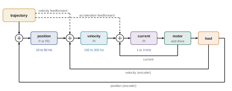
Almost every robot joint runs a cascade of three nested loops, each faster than the one around it:
- The current (torque) loop, usually a PI controller in the drive, runs at 10 to 40 kHz with a bandwidth of 1 to 3 kHz. It turns a current command into motor current despite back-EMF and winding inductance.
- The velocity loop, typically PI, runs at 2 to 10 kHz with a bandwidth of 100 to 300 Hz. It uses the encoder velocity and rejects friction and load disturbances.
- The position loop, typically P or PD with feedforward, runs at 1 to 4 kHz with a bandwidth of 10 to 50 Hz.
Each inner loop, closed and fast, looks to the outer loop like a near-ideal actuator: the velocity loop sees a torque source, the position loop sees a velocity source. The design rule is bandwidth separation, each loop five to ten times slower than the loop inside it, so the loops can be tuned one at a time from the inside out. Feedforward enters at every level: acceleration feedforward as a torque command to the current loop, velocity feedforward to the velocity loop. With a P position loop of gain \( K_v \) (in s⁻¹) around an ideal velocity loop, the following error at constant speed v without velocity feedforward is \( v/K_v \), which is why feedforward is essential for path accuracy.
Worked problem
Bandwidth separation and following error
A joint's current loop closes at 2 kHz. Choose velocity and position loop bandwidths with a separation factor of 6, and find the following error at 1.2 rad/s with a P position loop whose gain equals its bandwidth in rad/s, without velocity feedforward.
Show solution
- Velocity loop: 2000/6 ≈ 330 Hz. Position loop: 330/6 ≈ 55 Hz, or \( K_v = 2\pi \times 55 = 345 \) s⁻¹.
- Following error: \( v/K_v = 1.2/345 = 3.5 \times 10^{-3} \) rad.
Answer: Velocity loop about 330 Hz and position loop about 55 Hz. Without feedforward the joint trails its reference by 3.5 mrad at 1.2 rad/s, about 2.8 mm at 0.8 m radius; velocity feedforward removes almost all of it. In practice the position bandwidth would also be limited by structural resonance, as lesson 3 showed.
Digital implementation
Controllers designed in continuous time must be discretized (ROB-230). For a PID, a standard form updates at each sample k with sample time h:
with the derivative usually filtered and taken on the measurement, and the integrator clamped for anti-windup. The Tustin (bilinear) transformation \( s \to \frac{2}{h}\frac{z - 1}{z + 1} \) preserves stability and is preferred for filters and lead compensators. Several implementation details matter as much as the control law:
- Sample rate: at least 10 to 20 times the closed-loop bandwidth; slower rates lose phase margin through the zero-order hold's delay of about h/2 (ROB-230).
- Latency: the time from sampling the encoder to applying the new torque adds to the loop delay. Good practice computes the output as early in the cycle as possible and applies it at a fixed instant.
- Jitter: variation in sample timing acts like noise on the time base. Real-time operating systems and hardware timers keep it to microseconds; general-purpose operating systems may not (ROB-320).
- Quantization: encoder resolution limits position measurement, and differencing quantized positions makes noisy velocity. High-resolution encoders, observers (lesson 6) or time-stamped edge counting help.
- Numeric format: integer or fixed-point arithmetic on small microcontrollers needs scaling to avoid overflow and to keep small integrator increments from being rounded away.
Worked problem
Phase cost of sampling and delay
A position loop with crossover at 60 rad/s runs at 500 Hz with one sample of computation delay. Estimate the phase lost to the zero-order hold and the delay, and compare with a 4 kHz implementation.
Show solution
- At 500 Hz, h = 2 ms. Effective delay ≈ h/2 + h = 3 ms; phase loss \( 60 \times 0.003 = 0.18 \) rad = 10.3°.
- At 4 kHz, h = 0.25 ms. Effective delay 0.375 ms; phase loss \( 60 \times 0.000375 = 0.0225 \) rad = 1.3°.
Answer: About 10° at 500 Hz against 1.3° at 4 kHz. Ten degrees can turn a well-damped loop into a ringing one, which is why servo loops run at kilohertz rates even when the robot moves slowly.
Common mistakes
MistakeExpecting high gains to cure any model error
InsteadGains are limited by resonances and delay; reduce large model errors by identification or adaptation.
MistakeUsing a pure sign function in sliding mode control
InsteadUse a boundary layer to avoid chattering.
MistakeIdentifying parameters from a slow, single-frequency motion
InsteadUse persistently exciting trajectories; check the regressor condition number.
MistakeTuning cascaded loops from the outside in
InsteadTune the current loop first, then velocity, then position, keeping a bandwidth separation of five to ten.
MistakeIgnoring latency and jitter in the digital controller
InsteadCount sampling, computation and bus delays in the phase budget and use real-time scheduling.
Summary and key terms
- Model error comes mainly from payload, friction, stiffness, inertial parameters and unmodelled dynamics.
- Feedback gains reduce model-error effects roughly as \( 1/\omega_n^2 \), but bandwidth is limited by resonances and delay.
- Sliding mode control uses a switching term sized to the uncertainty bound, softened by a boundary layer.
- A disturbance observer estimates and cancels disturbances using a nominal model and a low-pass filter.
- Adaptive control and least-squares identification exploit linearity in parameters; estimates need persistent excitation.
- Cascaded current, velocity and position loops are tuned inside-out with five- to tenfold bandwidth separation, plus feedforward.
- Digital implementation needs adequate sample rates, low latency and jitter, careful differentiation and anti-windup.
- Robust control
- Control designed to perform despite bounded model uncertainty.
- Sliding mode control
- Robust control that drives a sliding variable to zero with a switching term.
- Boundary layer
- A thin region where the switching term is replaced by a linear one to avoid chattering.
- Disturbance observer
- An estimator of lumped disturbance torque from commanded torque and measured motion.
- Adaptive control
- Control that updates model parameters online from tracking errors.
- Persistent excitation
- A trajectory rich enough to reveal all model parameters.
- Parameter identification
- Estimating model parameters from recorded motion and torque data.
- Cascade control
- Nested loops in which each inner loop acts as an actuator for the outer one.
- Bandwidth separation
- Making each inner loop several times faster than the next outer loop.
- Jitter
- Variation in the timing of control samples.
Practice problems
Work each problem on paper first, then reveal the answer to check.
Doubling \( \omega_n \) in computed torque control changes model-error tracking error by what factor?
Show answer
It divides it by about four.
A sliding mode controller has \( |\eta|_{\max} \) = 3 rad/s². Suggest k.
Show answer
About 3.5 to 4 rad/s².
With λ = 10 s⁻¹ and residual error target 2 mrad, what boundary layer width?
Show answer
φ ≤ 0.02 rad/s.
A DOB with \( \hat{J} \) = 2 sees τ = 10 N·m and \( \ddot{q} \) = 4 rad/s². What is \( \hat{d} \)?
Show answer
2 N·m.
Why must identification trajectories be exciting?
Show answer
So every parameter affects the data and the least-squares problem is well conditioned.
Velocity loop 200 Hz with separation 5. Position loop bandwidth?
Show answer
About 40 Hz.
Following error for \( K_v \) = 100 s⁻¹ at 0.5 rad/s without feedforward?
Show answer
5 mrad.
In what order should cascaded loops be tuned?
Show answer
Current, then velocity, then position.
What delay does a zero-order hold add, roughly?
Show answer
Half a sample period.
Phase loss of 2 ms delay at 50 rad/s crossover?
Show answer
0.1 rad, about 5.7°.
Lesson quiz · 5 questions
Score 60% or more to complete this lesson.
Create a free account to save your progress, take quizzes and earn a certificate.