
ROB-300 · Lesson 9 of 12 · 35 min
Trajectory tracking and computed torque control
With a smooth trajectory in hand, the controller's job is to make the robot follow it closely. Pure feedback, as in the PID loops of lesson 4, reacts only after an error has appeared; to follow a fast trajectory it needs a large error to generate the large torque the motion requires, so it always lags. The cure is to predict the torque the trajectory needs and apply it in advance, leaving feedback to correct only what the prediction gets wrong. This lesson develops that idea in stages: gravity compensation, which removes the steady sag of PD control; feedforward of the full dynamic model along the desired trajectory; and computed torque control, also called inverse dynamics control, which cancels the nonlinear dynamics so that every joint behaves like a simple, decoupled double integrator. It ends with what happens when the model is wrong, which it always is to some degree.
Why feedback alone lags
Consider a joint under PD control asked to follow \( q_d(t) = A\sin\omega t \). In steady state the torque required is roughly \( J\ddot{q}_d = -JA\omega^2\sin\omega t \), and a PD controller can only produce torque from error, \( \tau = K_pe + K_d\dot{e} \). The tracking error must therefore be about \( J\omega^2A/K_p \) in amplitude for low frequencies. Faster or larger motions mean larger errors, and raising the gains to shrink them is limited by stability, noise and resonances. Feedback is excellent at rejecting unpredictable disturbances; it is a poor way to generate predictable torques.
Worked problem
Tracking error under PD control
A joint with J = 1.5 kg·m², PD gains \( K_p \) = 600 N·m/rad and \( K_d \) = 59.5 N·m·s/rad follows \( q_d = 0.5\sin(4t) \) rad. Estimate the steady tracking error amplitude, ignoring gravity.
Show solution
- Error transfer function from reference: \( E/Q_d = (Js^2 + bs)/(Js^2 + (b + K_d)s + K_p) \), with b = 0.5.
- At ω = 4: numerator magnitude \( |{-1.5 \times 16} + j0.5 \times 4| = |-24 + 2j| = 24.1 \).
- Denominator: \( |600 - 24 + j60 \times 4| = |576 + 240j| = 624 \).
- Error amplitude: \( 0.5 \times 24.1/624 = 0.0193 \) rad.
Answer: About 0.019 rad (1.1°), almost 4 % of the motion amplitude, and the error leads or lags the reference throughout. At the end of an arm 0.8 m long that is 15 mm, far too large for most tasks. Doubling the frequency would roughly quadruple it.
PD control with gravity compensation
The simplest model-based improvement adds the gravity vector to a PD law:
where \( \mathbf{e} = \mathbf{q}_d - \mathbf{q} \) for a constant target \( \mathbf{q}_d \). Gravity is now cancelled at every configuration, so there is no steady sag and no need for integral action to fight it. A classic result by Takegaki and Arimoto, published in 1981, shows that for any positive-definite diagonal gains this controller drives a rigid manipulator to any constant target from any initial state, using the energy-like function \( V = \tfrac{1}{2}\dot{\mathbf{q}}^{\mathsf{T}}\mathbf{M}\dot{\mathbf{q}} + \tfrac{1}{2}\mathbf{e}^{\mathsf{T}}\mathbf{K}_p\mathbf{e} \) and the skew-symmetry property of lesson 2. The proof never needs the inertia matrix or Coriolis terms to be known, only gravity. Gravity compensation is used in almost every industrial and collaborative robot; it is also what lets a collaborative arm be pushed around by hand in 'free drive' mode, where the controller cancels gravity and applies no position feedback at all.
Worked problem
Gravity compensation torques
For the two-link arm of lesson 2, compute the gravity compensation torques at \( q_1 = 30° \), \( q_2 = 45° \).
Show solution
- \( c_1 = \cos 30° = 0.866 \); \( c_{12} = \cos 75° = 0.259 \).
- \( g_1 = (3 \times 0.2 + 2 \times 0.4) \times 9.81 \times 0.866 + 2 \times 0.15 \times 9.81 \times 0.259 = 11.89 + 0.762 = 12.66 \) N·m.
- \( g_2 = 2 \times 0.15 \times 9.81 \times 0.259 = 0.762 \) N·m.
Answer: \( \mathbf{g} = [12.66, 0.76] \) N·m. Added to a PD law, these remove the steady error the PD controller would otherwise have: with \( K_p \) = 600, the shoulder would sag by 0.021 rad without compensation.
Feedforward along the trajectory
For tracking, add the torque the desired trajectory needs, computed from the model by inverse dynamics, to a PD feedback law:
Because the feedforward depends only on the desired trajectory, it can be computed in advance, which is attractive when computation is limited. If the model is exact and the robot starts on the trajectory, the feedforward produces exactly the planned motion and the feedback has nothing to do. In practice it removes the bulk of the tracking error, and the feedback handles model error, friction and disturbances. Most industrial controllers use some form of this structure, often with friction feedforward added.
Worked problem
Feedforward torque for a single link
The single link of lesson 1 (I = 0.18 kg·m², \( mgl_c \) = 5.34 N·m, q measured from horizontal) follows \( q_d = 0.6\sin(3t) \) rad. Find the feedforward torque at t = 0 and at t = π/6 s.
Show solution
- \( \ddot{q}_d = -5.4\sin(3t) \). Feedforward: \( \tau_{ff} = 0.18\ddot{q}_d + 5.34\cos q_d \).
- t = 0: \( q_d = 0 \), \( \ddot{q}_d = 0 \); \( \tau_{ff} = 5.34 \) N·m (gravity only).
- t = π/6: \( 3t = \pi/2 \), so \( q_d = 0.6 \) rad and \( \ddot{q}_d = -5.4 \) rad/s². \( \tau_{ff} = 0.18 \times (-5.4) + 5.34\cos 0.6 = -0.972 + 4.41 = 3.43 \) N·m.
Answer: 5.34 N·m at t = 0 and 3.43 N·m at t = π/6 s. A feedback-only controller would have to generate these torques from error, whereas feedforward supplies them directly.
Computed torque control
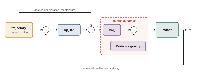
Computed torque control goes one step further: it evaluates the model at the actual state and uses it to cancel the nonlinear dynamics completely. Choose
Substituting into the manipulator equation \( \mathbf{M}\ddot{\mathbf{q}} + \mathbf{C}\dot{\mathbf{q}} + \mathbf{g} = \boldsymbol{\tau} \), the C and g terms cancel and, since M is invertible, \( \ddot{\mathbf{q}} = \mathbf{v} \). The closed loop becomes
a set of independent, linear, second-order error equations, one per joint, identical in every configuration and at every speed. With diagonal gains \( K_{p,i} = \omega_n^2 \) and \( K_{d,i} = 2\zeta\omega_n \), every joint's error decays like a critically damped spring whatever the arm is doing. Note that these gains are in units of acceleration, not torque: the inertia matrix scales them to torque automatically, which is why computed torque control needs no gain scheduling. The method is an example of feedback linearization: a nonlinear system made linear by a nonlinear feedback law.
Worked problem
Computed torque gains and torque
For the two-link arm, choose computed torque gains for \( \omega_n \) = 25 rad/s and critical damping. At the instant when \( \mathbf{q} = [0, \pi/2] \), \( \dot{\mathbf{q}} = \mathbf{0} \), \( \ddot{\mathbf{q}}_d = [2, -1] \) rad/s² and the errors are zero, find the commanded torques.
Show solution
- Gains: \( K_p = 625 \) s⁻², \( K_d = 50 \) s⁻¹ on each joint.
- With zero error, \( \mathbf{v} = \ddot{\mathbf{q}}_d = [2, -1] \).
- At \( q_2 = 90° \), \( \mathbf{M} = [[0.54, 0.06], [0.06, 0.06]] \) (lesson 2); \( \mathbf{M}\mathbf{v} = [1.08 - 0.06, 0.12 - 0.06] = [1.02, 0.06] \).
- Velocities are zero, so C\( \dot{\mathbf{q}} \) = 0; gravity \( \mathbf{g} = [13.73, 0] \) (lesson 2).
- \( \boldsymbol{\tau} = [14.75, 0.06] \) N·m.
Answer: τ ≈ [14.75, 0.06] N·m. The elbow needs almost nothing because link 2 is balanced over its joint and its commanded deceleration is nearly offset by the inertial coupling from the shoulder's acceleration, a subtlety a joint-by-joint controller would miss.
The effect of model error
Computed torque control is only as good as its model. Suppose the controller uses estimates \( \hat{\mathbf{M}}, \hat{\mathbf{C}}, \hat{\mathbf{g}} \). The closed loop becomes
The mismatch acts as a disturbance η driving the otherwise perfect error dynamics. Small errors give small tracking errors, reduced further by high gains; large errors, such as an unmodelled payload, can degrade tracking badly. Friction is usually the largest unmodelled term and is added explicitly as a friction-compensation torque. Lesson 11 discusses robust and adaptive methods that keep performance despite model error. In practice, computed torque control is used with carefully identified models, and many industrial robots use the simpler feedforward form, which degrades more gracefully because it does not feed measured noise into the model terms.
Worked problem
Payload error as a disturbance
A single-link arm's model omits a 1 kg payload at 0.5 m, so \( I - \hat{I} = 0.25 \) kg·m² and \( mgl - \widehat{mgl} = 4.9 \) N·m. With true I = 0.43 kg·m², computed torque gains \( K_p = 400 \) s⁻² and the arm holding still and horizontal, find the steady error.
Show solution
- At rest, v = \( K_pe \), and the disturbance is \( \eta = [(I - \hat{I})K_pe + 4.9]/I \).
- Closed loop at rest: \( K_pe = \eta \), so \( 400e = (0.25 \times 400e + 4.9)/0.43 \).
- \( 172e = 100e + 4.9 \), so \( e = 4.9/72 = 0.068 \) rad.
Answer: About 0.068 rad (3.9°). The missing gravity term causes the sag, and the missing inertia makes it worse by weakening the effective feedback gain. Integral action, payload identification or a robust term (lesson 11) would remove it.
Simulation: PD versus computed torque
The code below simulates the two-link arm following a quintic move of both joints, first with PD control plus gravity compensation (gains in torque units, scaled for the stretched-out arm), and then with computed torque control using the exact model. It reports the largest tracking error during the move.
import numpy as np
m1, m2, l1, lc1, lc2, I1, I2, g = 3, 2, 0.4, 0.2, 0.15, 0.04, 0.015, 9.81
a = I1 + I2 + m1*lc1**2 + m2*(l1**2 + lc2**2); b = m2*l1*lc2; d = I2 + m2*lc2**2
M = lambda q: np.array([[a + 2*b*np.cos(q[1]), d + b*np.cos(q[1])], [d + b*np.cos(q[1]), d]])
Cv = lambda q, qd: np.array([-b*np.sin(q[1])*(2*qd[0]*qd[1] + qd[1]**2), b*np.sin(q[1])*qd[0]**2])
G = lambda q: np.array([(m1*lc1 + m2*l1)*g*np.cos(q[0]) + m2*lc2*g*np.cos(q[0] + q[1]), m2*lc2*g*np.cos(q[0] + q[1])])
q0, qf, T = np.array([0.0, 0.5]), np.array([1.2, 1.8]), 1.0
def ref(t):
    s = min(t/T, 1.0); D = qf - q0
    return (q0 + D*(10*s**3 - 15*s**4 + 6*s**5), D/T*(30*s**2 - 60*s**3 + 30*s**4),
            D/T**2*(60*s - 180*s**2 + 120*s**3))
wn = 25.0
def run(mode, h=2e-4):
    q, qd, emax = q0.copy(), np.zeros(2), 0.0
    for k in range(int(1.5/h)):
        r, rd, rdd = ref(k*h); e, ed = r - q, rd - qd
        if mode == "pd":
            Mmax = M(np.zeros(2)).diagonal()
            tau = Mmax*wn**2*e + Mmax*2*wn*ed + G(q)
        else:
            tau = M(q) @ (rdd + 2*wn*ed + wn**2*e) + Cv(q, qd) + G(q)
        qdd = np.linalg.solve(M(q), tau - Cv(q, qd) - G(q))
        q, qd = q + h*qd, qd + h*qdd
        emax = max(emax, abs(e).max())
    return emax
print(f"PD + gravity:    max error {run('pd')*1000:7.2f} mrad")
print(f"computed torque: max error {run('ct')*1000:7.2f} mrad")PD + gravity: max error 43.74 mrad computed torque: max error 0.06 mrad
With PD plus gravity compensation the arm lags its reference by tens of milliradians during the move, because feedback must generate the inertial and coupling torques from error. Computed torque control with an exact model tracks to within numerical integration error. Real results lie between: with a good identified model, computed torque or feedforward control typically cuts tracking error by a factor of five to twenty compared with PD alone.
Task-space control
Computed torque control can also be written in task space, where the error is the tool's position and orientation rather than joint angles. Khatib's operational-space formulation, from 1987, defines a task-space inertia \( \boldsymbol{\Lambda} = (\mathbf{J}\mathbf{M}^{-1}\mathbf{J}^{\mathsf{T}})^{-1} \) and computes joint torques \( \boldsymbol{\tau} = \mathbf{J}^{\mathsf{T}}\mathbf{F} \) from a task-space force F that cancels task-space dynamics. This makes the tool behave as a chosen mass-spring-damper in Cartesian space, which leads directly to the impedance control of lesson 10. For redundant robots, extra joint motions can be controlled in the null space of the Jacobian (ROB-210) without disturbing the tool.
Common mistakes
MistakeRelying on high feedback gains to track fast trajectories
InsteadAdd model-based feedforward so feedback only corrects small errors.
MistakeUsing computed torque gains as if they were torque gains
InsteadComputed torque gains are in acceleration units; M(q) scales them to torque.
MistakeAssuming computed torque control is robust to large model errors
InsteadModel mismatch acts as a disturbance; identify the model and add friction compensation or robust terms.
MistakeForgetting gravity compensation in PD control
InsteadAdd g(q) to remove sag without needing integral action.
MistakeComputing feedforward from measured rather than desired states and then wondering about noise
InsteadFeedforward from the desired trajectory avoids injecting sensor noise into the model terms.
Summary and key terms
- Feedback alone must generate motion torques from error, so it lags fast trajectories.
- PD plus gravity compensation removes sag and is globally stable for set-points (Takegaki and Arimoto).
- Feedforward of the inverse dynamics along the desired trajectory supplies most of the torque in advance.
- Computed torque control cancels M, C and g, giving decoupled linear error dynamics \( \ddot{e} + K_d\dot{e} + K_pe = 0 \).
- Computed torque gains are acceleration gains, so no gain scheduling is needed.
- Model errors appear as a disturbance η; payload and friction errors are the most common.
- Task-space versions such as operational-space control apply the same idea to the tool pose.
- Gravity compensation
- Adding g(q) to cancel gravity torques.
- Feedforward
- Torque computed from the desired trajectory and applied in advance.
- Inverse dynamics
- Computing the torque that produces a given motion from the model.
- Computed torque control
- Cancelling robot dynamics with a model so error dynamics become linear.
- Feedback linearization
- Using nonlinear feedback to make a nonlinear system behave linearly.
- Decoupling
- Making each joint's error independent of the others.
- Model mismatch
- The difference between the true and modelled dynamics.
- Free drive
- A mode in which gravity is cancelled so a person can move the robot by hand.
- Operational-space control
- Computed torque control formulated in task-space coordinates.
- Task-space inertia
- The inertia felt at the tool, \( (JM^{-1}J^{\mathsf{T}})^{-1} \).
Practice problems
Work each problem on paper first, then reveal the answer to check.
Why does a PD controller lag a sinusoidal trajectory?
Show answer
It needs error to generate the torque the motion requires.
Write the PD-plus-gravity control law.
Show answer
\( \tau = K_pe - K_d\dot{q} + g(q) \).
Feedforward for a link with I = 0.2, \( mgl_c \) = 4 N·m at \( q_d = 0 \), \( \ddot{q}_d = 10 \).
Show answer
2 + 4 = 6 N·m.
Computed torque gains for \( \omega_n \) = 30 rad/s, ζ = 1?
Show answer
\( K_p = 900 \) s⁻², \( K_d = 60 \) s⁻¹.
After perfect computed torque cancellation, what equation does each joint error obey?
Show answer
\( \ddot{e} + K_d\dot{e} + K_pe = 0 \).
Why does computed torque control not need gain scheduling?
Show answer
M(q) scales the acceleration command to torque in every configuration.
What acts as a disturbance in computed torque control with an imperfect model?
Show answer
The model mismatch η.
Which term is usually the largest unmodelled effect?
Show answer
Friction.
What does free-drive mode cancel?
Show answer
Gravity, so the arm can be moved by hand.
Name one advantage of feedforward from the desired trajectory.
Show answer
It can be precomputed and does not amplify measurement noise.
Lesson quiz · 5 questions
Score 60% or more to complete this lesson.
Create a free account to save your progress, take quizzes and earn a certificate.