
ROB-440 · Lesson 3 of 12 · 34 min
End effectors and tooling integration
The end effector is the part of a robot cell that touches the product, and it is usually the part that is custom-designed for each project. Robots are bought from a catalogue; grippers, welding torches, dispensing heads and vacuum tools are often engineered or at least configured for the specific parts. ROB-400 analysed grasping from first principles: contact mechanics, force closure, finger geometry and the basic sizing of grip and suction forces. This lesson takes the integrator's view of tooling: how a complete tool stack is assembled on the robot flange, how its mass and inertia are checked against the robot's limits, how compressed air and electric tools are supplied and controlled, how tool changers and compliance devices work, and how process tools such as welding torches and dispensers are integrated. A good end effector is light, stiff, simple to maintain, and safe when power or air is lost.
The tool stack
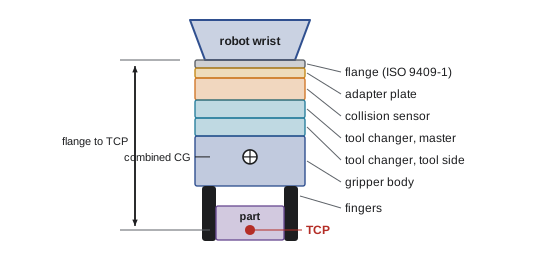
Between the robot's mechanical interface and the part, several components are usually stacked. The robot flange follows a standard bolt pattern, commonly ISO 9409-1, which defines the pitch circle, bolt holes and locating pin for each flange size. On it may sit an adapter plate, a collision sensor or breakaway, a tool changer master plate, a force-torque sensor, the tool changer tool plate, and finally the gripper or process tool with its fingers or nozzles. Each item adds mass, length and cost, and each joint adds a little compliance and a little positioning error.
| Component | Purpose | Typical mass range | Design notes |
|---|---|---|---|
| Adapter plate | Matches the robot flange to the next component | 0.1 to 1 kg | Aluminium; keep thin; include dowel pins for repeatable mounting |
| Collision sensor or breakaway | Trips the robot stop if the tool hits something, and limits damage | 0.3 to 2 kg | Many modern robots detect collisions from motor currents instead |
| Tool changer | Lets the robot swap tools automatically, passing air, signals and power | 0.3 to 10 kg for the pair | Fail-safe locking so the tool cannot drop on air loss |
| Force-torque sensor | Measures six components of force and torque at the wrist | 0.2 to 1.5 kg | Needed for force-controlled assembly, polishing and hand guiding |
| Gripper or tool body | Performs the task | 0.2 to 50 kg | The largest mass; optimize with pockets and light materials |
| Fingers, cups or nozzles | Contact the part | Grams to several kilograms | Often 3D printed or machined per part variant |
The tool centre point (TCP) is the point on the tool whose position and orientation the robot program controls, such as the centre between gripper fingers, the tip of a welding wire or the centre of a suction cup face. Lesson 4 explains how the TCP is defined and calibrated. A long tool stack moves the TCP far from the wrist, which magnifies small angular errors in the wrist joints into larger position errors at the tip and raises the static and dynamic torques on the wrist axes.
Checking mass, centre of gravity and inertia
Lesson 1 checked static wrist torque. A complete check also includes the combined centre of gravity of the tool and part, and the moment of inertia about each wrist axis, which limits how quickly the wrist can accelerate the load. Robot manufacturers publish allowable moments of inertia for axes 4, 5 and 6 in kilogram square metres, and their controllers need correct payload data to plan motions; a wrong payload setting causes poor path accuracy, vibration, false collision detection or premature gearbox wear.
The combined centre of gravity of several components along the flange axis is the mass-weighted average of their individual positions. The moment of inertia about a wrist axis is the sum, for each component, of its own inertia about its centre of gravity plus its mass times the square of the distance from the axis, the parallel axis theorem.
Worked problem
Combined payload data for the robot controller
A tool stack has a 1.2 kg tool changer pair with its centre of gravity 25 mm from the flange, a 4.5 kg gripper at 110 mm, and a 6.0 kg part at 220 mm, all on the flange axis. Treat each component as a point mass for a first estimate, and find the total mass, combined centre of gravity, and moment of inertia about axis 5, which passes through the wrist centre 110 mm behind the flange.
Show solution
- Total mass: \( 1.2 + 4.5 + 6.0 = 11.7 \) kg.
- Combined centre of gravity: \( (1.2 \times 25 + 4.5 \times 110 + 6.0 \times 220)/11.7 = (30 + 495 + 1320)/11.7 \approx 158 \) mm from the flange.
- Distances from axis 5: \( 135 \), \( 220 \) and \( 330 \) mm.
- Inertia about axis 5: \( 1.2(0.135)^2 + 4.5(0.220)^2 + 6.0(0.330)^2 \approx 0.022 + 0.218 + 0.653 = 0.89 \) kg·m².
- The real gripper and part have their own inertia about their centres of gravity, so the true value is somewhat higher; CAD mass properties give exact values.
Answer: About 11.7 kg with its centre of gravity 158 mm from the flange and roughly 0.9 kg·m² about axis 5, to be compared with the datasheet allowance and entered as payload data.
# Payload data from a list of tool components (CAD-style mass properties)
import numpy as np
# name, mass kg, centre of gravity (x, y, z) mm from flange, own inertia about cg (Ixx, Iyy, Izz) kg m^2
parts = [("changer", 1.2, (0, 0, 25), (0.0010, 0.0010, 0.0015)),
         ("gripper", 4.5, (0, 15, 110), (0.0200, 0.0150, 0.0120)),
         ("part",    6.0, (0, 0, 220), (0.0300, 0.0300, 0.0100))]
m = sum(p[1] for p in parts)
cg = sum(p[1] * np.array(p[2]) for p in parts) / m
I = np.zeros(3)
for name, mi, c, Icg in parts:
    d = (np.array(c) - cg) / 1000                    # m, offset from combined cg
    I += np.array(Icg) + mi * np.array([d[1]**2 + d[2]**2, d[0]**2 + d[2]**2, d[0]**2 + d[1]**2])
print(f"mass {m:.1f} kg, cg (x, y, z) = ({cg[0]:.0f}, {cg[1]:.1f}, {cg[2]:.0f}) mm")
print("inertia about combined cg (Ixx, Iyy, Izz) kg m^2:", np.round(I, 3))mass 11.7 kg, cg (x, y, z) = (0, 5.8, 158) mm inertia about combined cg (Ixx, Iyy, Izz) kg m^2: [0.106 0.101 0.024]
Most robot controllers can also estimate payload automatically by moving the wrist through a test motion and measuring motor torques. This is useful for checking the entered data, but the estimate is only as good as the robot's dynamic model and the test motion, so integrators still calculate the expected values from CAD.
Pneumatic and electric grippers
Most industrial grippers are pneumatic: compressed air at typically 4 to 7 bar drives a piston that opens or closes the jaws. Pneumatic grippers are simple, robust, powerful for their size and inexpensive. Electric grippers use a motor and screw or a servo drive; they cost more but allow programmable force, position and speed, report jaw position for part verification, and avoid the energy losses of compressed air. Compressed air is one of the most expensive utilities in a plant, because compressors convert only a small fraction of their electrical input into useful work at the tool.
| Property | Pneumatic gripper | Electric gripper |
|---|---|---|
| Force control | Set by pressure regulator; fixed during operation | Programmable per part and per step |
| Position feedback | Usually open or closed sensors only | Continuous jaw position; can measure parts |
| Speed | Very fast | Fast; programmable |
| Power-loss behaviour | Depends on valve type and springs; can be made to hold | Self-locking screws or brakes can hold; check the design |
| Running cost | Compressed air is expensive per unit of useful work | Low electrical consumption |
| Purchase cost | Lower | Higher |
| Integration | Valves, tubing and sensors | Cable and fieldbus or I/O |
Worked problem
Air consumption of a pneumatic gripper
A double-acting gripper has a piston bore of 40 mm and a stroke of 12 mm, and cycles once every 6 s at 6 bar gauge pressure, 24 hours a day. Ignoring tubing volume, estimate the free-air consumption per year.
Show solution
- Swept volume per stroke: \( \pi (0.020)^2 \times 0.012 \approx 1.51 \times 10^{-5} \) m³, or 15.1 cm³.
- Double-acting: two strokes per cycle, \( 30.2 \) cm³ of compressed air per cycle.
- Free air at 6 bar gauge is about \( (6 + 1.013)/1.013 \approx 6.9 \) times the compressed volume: about 208 cm³ of free air per cycle.
- Cycles per year: \( 365 \times 24 \times 3600 / 6 \approx 5.26 \) million.
- Annual free air: \( 208 \times 5.26 \times 10^{6} \) cm³ \( \approx 1100 \) m³.
Answer: About 1,100 m³ of free air per year for the gripper alone; tubing volume often adds 20 to 50 per cent, and leaks in the plant usually waste far more.
Vacuum tools are the other dominant gripper family, especially in packaging, palletizing, sheet metal and glass handling. Vacuum is produced either by venturi ejectors, which use compressed air and need no moving parts, or by electric vacuum pumps and blowers. Venturi ejectors are simple and fast but consume considerable compressed air; air-saving ejectors switch off the supply once vacuum is reached and a check valve holds it, restarting only if vacuum decays.
Worked problem
Vacuum tool for a fast palletizer
A palletizer lifts 18 kg cartons with a foam vacuum pad of effective area 0.04 m² at a vacuum of 0.25 bar below atmospheric pressure. The robot accelerates the carton upward at up to 5 m/s². Using a safety factor of 2 on vertical lift, is the pad adequate? Use ROB-400's basic suction relation.
Show solution
- Holding force: \( F = \Delta p \times A = 25\,000 \times 0.04 = 1000 \) N.
- Required force during upward acceleration: \( m(g + a) = 18 \times (9.81 + 5) \approx 267 \) N.
- With a safety factor of 2: \( 533 \) N required.
- Margin: \( 1000 / 533 \approx 1.9 \) times the required value, before considering leakage through the porous carton.
- Corrugated board leaks; a supplier test at the real vacuum level is needed to confirm the achieved vacuum on the actual cartons.
Answer: Yes on paper, at about 1.9 times the requirement with the safety factor included; confirm achieved vacuum on real cartons, and consider rotational motions, which load the pad in shear.
Fail-safe behaviour and pneumatic circuits
What happens if the air supply or power fails while the robot holds a part? With a single-solenoid, spring-return valve, the gripper may open when the solenoid loses power and drop the part. With a double-solenoid detented valve, the valve stays in its last position, and the gripper stays closed as long as pressure remains in the cylinder. Pilot-operated check valves on the gripper ports, or grippers with internal springs, hold the part even if air pressure is lost. For vacuum tools, a check valve and a vacuum reservoir can hold the part briefly, and the robot can be programmed to lower it before release. The right answer depends on the risk assessment: dropping a heavy part may be dangerous, but a gripper that cannot be opened during a rescue is also a hazard. Designers document the intended behaviour on power loss, air loss and emergency stop for every actuator.
# Hold time of a vacuum tool after the supply stops, with a reservoir and a leak
import numpy as np
V = 0.004            # m^3 of volume under vacuum (cups, hoses, reservoir)
p_atm = 101_325.0    # Pa
p0 = p_atm - 60_000  # starting absolute pressure (60 kPa vacuum)
leak = 1.0e-4        # m^3/s of air leaking in through the porous carton (assumed constant)
area, mass = 0.04, 18.0
p_needed = p_atm - 2 * mass * (9.81 + 5.0) / area   # SF 2 with 5 m/s^2 upward acceleration
# isothermal: mass inflow raises pressure; dp/dt = p_atm * leak / V
dpdt = p_atm * leak / V
t_hold = (p_needed - p0) / dpdt
print(f"vacuum needed for SF 2 while accelerating: {(p_atm - p_needed)/1000:.1f} kPa")
print(f"time until that limit after supply loss: {t_hold:.1f} s")vacuum needed for SF 2 while accelerating: 13.3 kPa time until that limit after supply loss: 18.4 s
With these assumed numbers the tool keeps a safe grip for about 18 seconds after the supply stops, which is long enough for a programmed set-down if the robot can still move, but not long enough to leave a carton hanging during a lengthy stop. Real leakage through corrugated board varies widely with board grade and humidity, so integrators measure it. A vacuum switch that warns the robot when the level falls toward the limit lets the program react before the carton drops.
Tool changers
Automatic tool changers let one robot use several end effectors: different grippers for different parts, or a gripper and a deburring spindle. A changer consists of a master plate on the robot and a tool plate on each tool. Locking is usually by pneumatically driven balls or a cam, designed so that the lock holds mechanically if air is lost. Modules on the sides pass compressed air, vacuum, electrical signals, power, fieldbus or coolant. Each tool sits in a tool stand with sensors confirming its presence, and the robot program checks that the correct tool is locked before continuing.
Tool changers add mass and cost, and a changeover takes several seconds, so they make sense when the alternative is a second robot or a long manual changeover. Manual quick-change systems, which lock with a lever but still provide repeatable location and utility connections, are a cheaper option for changeovers a few times a shift. For tool identification, many systems include coded pins or an electronic ID chip, so that the PLC can confirm the correct tool and load the matching TCP and payload data automatically.
Compliance and collision protection
Robots are stiff position-controlled machines, and parts and fixtures are never perfectly placed. Compliance devices let the tool give a little when it meets resistance. A remote centre compliance (RCC) device places its centre of compliance near the tip of a peg, so that lateral and angular misalignment during insertion is corrected by contact forces rather than causing jamming. Floating units and spring-loaded fingers serve similar purposes. Active compliance, using a force-torque sensor and force control as described in ROB-300, provides programmable behaviour at higher cost.
Collision protection limits damage when something goes wrong. A breakaway unit holds the tool rigidly with spring or air pressure until an overload, then deflects and opens a switch that stops the robot. Many current robots instead detect collisions from unexpected motor currents, which needs no extra hardware but depends on correct payload data. Neither is a safety function for protecting people unless it is specifically rated as such; Lesson 8 explains the difference.
Process tools
Not every end effector grips. Arc welding robots carry a torch connected to a wire feeder and power source through a cable called a hose package or dress pack, routed through or along the arm. Torch cleaning stations ream spatter from the nozzle, trim the wire and apply anti-spatter fluid at intervals. Through-arm torches on hollow-wrist robots reduce cable wear and interference. Dispensing tools for adhesives and sealants use metering pumps whose flow must be coordinated with robot speed so that the bead cross-section stays constant even when the robot slows at corners. Spindles for deburring and polishing need compliance to follow edges. Screwdriving tools monitor torque and angle to verify each joint.
Worked problem
Bead size and robot speed
A sealant bead must have a cross-sectional area of 12 mm². The dispenser delivers 3.0 cm³/s at full output. What robot path speed gives the correct bead, and what must happen at corners where the robot slows to 40 per cent of that speed?
Show solution
- Flow equals area times speed: \( v = Q/A = 3000 \text{ mm}^3/\text{s} \div 12 \text{ mm}^2 = 250 \) mm/s.
- At corners the robot moves at 100 mm/s, so with constant flow the bead area would grow to 30 mm².
- The dispenser flow must follow the robot's actual TCP speed, scaling to 1.2 cm³/s at corners.
- Most robot controllers provide an analog or fieldbus output proportional to TCP speed for this purpose.
Answer: 250 mm/s, with dispenser flow scaled to actual TCP speed so that corners do not get oversized beads.
Dress packs deserve design attention. Hoses and cables flex millions of times over a robot's life, and failures of cables at the wrist are among the most common causes of downtime. Integrators use dress pack systems with retractors and protective sleeves, simulate cable motion where possible, and avoid programs that wind axis 6 repeatedly past its full rotation.
Common mistakes
MistakeEntering only the part mass as payload data.
InsteadEnter the full tool stack mass, combined centre of gravity and inertia, verified against CAD and a controller estimate.
MistakeAssuming any gripper will hold its part when air is lost.
InsteadSpecify and test the behaviour on air loss, power loss and emergency stop, using check valves, springs or detented valves as the risk assessment requires.
MistakeSizing vacuum pads for static lift only.
InsteadInclude acceleration, rotation and leakage, and test the achieved vacuum on real parts.
MistakeRunning dispensers at constant flow.
InsteadTie flow to actual TCP speed so that bead size stays constant through corners.
MistakeTreating a breakaway or current-based collision detection as personnel protection.
InsteadThese protect equipment; people need safety-rated functions selected through the risk assessment.
Summary and key terms
- A tool stack can include an adapter, collision sensor, tool changer, force-torque sensor, gripper and fingers, on an ISO 9409-1 flange.
- Correct payload data, including combined centre of gravity and inertia, is essential for path accuracy, collision detection and gearbox life.
- Pneumatic grippers are simple and cheap; electric grippers give programmable force and position feedback at lower running cost.
- Vacuum tools must be sized for acceleration and leakage, and air-saving ejectors reduce consumption.
- Behaviour on loss of air, power and emergency stop must be designed and documented for each actuator.
- Tool changers pass utilities and must lock fail-safe; compliance devices and collision sensors protect parts and tools.
- Process tools such as welding torches and dispensers need coordinated control and well-designed dress packs.
- End effector
- The device at the end of the robot arm that interacts with the work, such as a gripper or torch.
- ISO 9409-1
- The standard for robot mechanical interface flanges.
- Tool centre point (TCP)
- The point on the tool whose pose the robot program controls.
- Parallel axis theorem
- Inertia about an axis equals inertia about the centre of gravity plus mass times distance squared.
- Venturi ejector
- A device that produces vacuum from compressed air flowing through a nozzle.
- Tool changer
- A coupling that lets a robot automatically exchange end effectors with their utilities.
- Remote centre compliance (RCC)
- A passive device that lets a peg align itself during insertion.
- Dress pack
- The cables and hoses routed along a robot arm to its tool, with their supports.
Practice problems
Work each problem on paper first, then reveal the answer to check.
Components of 2 kg at 50 mm and 3 kg at 150 mm from the flange: combined centre of gravity?
Show answer
\( (100 + 450)/5 = 110 \) mm.
Why must payload data be correct in the controller?
Show answer
Path accuracy, vibration, collision detection and gearbox life depend on it.
A pad of 0.02 m² at 30 kPa vacuum: holding force?
Show answer
\( 30\,000 \times 0.02 = 600 \) N.
What valve choice keeps a pneumatic gripper closed if the solenoid loses power?
Show answer
A double-solenoid detented valve, ideally with pilot-operated check valves to hold on air loss.
Give one advantage of electric grippers.
Show answer
Programmable force and position with feedback, or lower energy cost.
What does an RCC device do?
Show answer
Lets a peg correct small lateral and angular misalignments during insertion.
A dispenser delivers 2 cm³/s and the bead must be 8 mm²: path speed?
Show answer
\( 2000/8 = 250 \) mm/s.
Why avoid winding axis 6 repeatedly past full rotation?
Show answer
It twists and wears cables and hoses in the dress pack.
Lesson quiz · 5 questions
Score 60% or more to complete this lesson.
Create a free account to save your progress, take quizzes and earn a certificate.