
CON-250 · Lesson 1 of 12 · 30 min
Surveying for construction: roles, datums and errors
Every building, road, pipe and parking lot starts as numbers on a drawing and ends as concrete, steel and asphalt in a particular place in the ground. Surveying is the discipline that connects the two. It tells the excavator operator how deep to dig, the formwork carpenter where to set the wall, the steel erector where the anchor bolts are and the owner whether the finished work is where it was meant to be. When layout goes wrong, the result is not a small inconvenience: a building over a property line, a sewer that runs uphill, a column grid that does not match the precast that was already cast in a plant two hundred kilometers away.
This course is about the surveying, layout and equipment knowledge that a construction manager, superintendent or field engineer needs. You will not become a licensed surveyor by taking it, but you will understand what surveyors do, how to check their work, how to set out a building from control, how to calculate earthwork quantities and how to choose, match and cost the machines that move the earth. This first lesson sets the foundations: who is responsible for what, how positions and heights are defined, and why every measurement contains error.
Who does the surveying on a construction project
Several different people measure things on a typical project, and their responsibilities are not interchangeable.
- The land surveyor. In the United States, only a licensed Professional Land Surveyor (PLS) may establish or re-establish legal property boundaries, prepare boundary and ALTA/NSPS land title surveys and certify the location of improvements. State boards license surveyors, and many states also require a licensed surveyor to stake the building corners or certify the foundation location.
- The construction or layout surveyor. Many contractors hire a survey firm, or keep a survey crew on staff, to lay out the work from the control network: gridlines, building corners, offsets, elevations, curb lines, pipe grades and anchor bolts. This work does not establish legal boundaries, so in most jurisdictions it does not need a license, but it must be done competently because the whole structure depends on it.
- The field engineer and the trades. Field engineers and foremen carry layout forward from the surveyor's marks: transferring gridlines up a building, setting embeds and sleeves, checking forms and setting batter boards. Most trades have someone who can run a builder's level, a rotating laser or a robotic total station.
- The engineer and the owner's inspector. The design engineer specifies tolerances and may require as-built surveys. Inspectors and testing agencies check elevations, grades and locations as part of quality assurance.
A construction manager's job is to make sure each of these roles is filled by someone competent, that everyone works from the same control and the same version of the drawings, and that critical layout is checked independently before anything permanent is built on it.
Plane surveying and geodetic surveying
The earth is not flat, but for a building site it may as well be. Plane surveying treats the area being surveyed as a flat surface with a vertical direction that is the same everywhere. Over a site a few hundred meters across, the error from ignoring the earth's curvature in horizontal distances is a tiny fraction of a millimeter per hundred meters, far smaller than the errors of the measurements themselves. Almost all construction layout is plane surveying.
Geodetic surveying accounts for the shape of the earth. It is needed for large control networks, long highways and pipelines, and for converting between coordinates measured by satellites and the flat grid coordinates used on drawings. You do not need to perform geodetic calculations, but you need to know that they sit underneath the coordinates on your drawings, because mistakes at that level can shift an entire site.
Curvature does matter for heights, even on small sites. Over a horizontal distance of 1 kilometer, a level line of sight rises about 78 millimeters above the curved level surface because of curvature, and atmospheric refraction bends the sight back down slightly, leaving a combined effect of about 68 millimeters. Over 100 meters the effect is less than a millimeter, which is one reason leveling is done with balanced, short sights.
Horizontal datums and coordinate systems
A coordinate means nothing without a datum: a defined origin, orientation and model of the earth. Modern horizontal datums are defined by a reference ellipsoid, a smooth mathematical surface that approximates the shape of the earth, and by a network of precisely located control points.
In the United States the national horizontal datum is NAD83, most recently in the NAD83(2011) realization maintained by the National Geodetic Survey (NGS). NGS is modernizing the National Spatial Reference System and plans to replace NAD83 with a new terrestrial reference frame (NATRF2022), which will shift coordinates by up to a couple of meters, so always confirm which datum and epoch a project uses. For engineering, coordinates are projected onto the State Plane Coordinate System (SPCS), with one or more zones per state. Note that the US survey foot was retired at the end of 2022 in favor of the international foot; they differ by two parts per million, which is about 1.2 meters over the large coordinate values of some state plane zones, so legacy data must be converted carefully.
Grid coordinates are usually given as northing and easting, in that order on most survey reports. They are large numbers because the origin of the projection is far away. Designers often use a local project coordinate system instead: a simple grid with an arbitrary origin, perhaps with gridline A-1 at coordinates 1000, 5000, rotated to match the building. This is easier to read but must be tied to the real-world grid through a documented transformation.
| Item | What it is | Why it matters on site |
|---|---|---|
| Ellipsoid | A smooth mathematical model of the earth's shape | GNSS receivers measure positions and heights relative to it |
| Map projection | A method of flattening latitude and longitude onto a grid | Introduces a scale factor: grid distances differ slightly from ground distances |
| Grid coordinates | Northing and easting on the projection | Used for the site plan, control points and GNSS work |
| Project coordinates | A local grid chosen by the designer | Simpler numbers; needs a documented tie to the grid |
| Scale factor | Ratio of grid distance to ground distance | Ignoring it can make long dimensions wrong by tens of millimeters |
The scale factor deserves attention. Because a projection cannot flatten a curved surface without stretching it, a distance on the grid is slightly different from the same distance measured on the ground. The combined scale factor, which also includes the effect of the site's height above the ellipsoid, is often between 0.9996 and 1.0002. That sounds trivial, but over 200 meters a scale factor of 0.9997 changes a dimension by 60 millimeters. Many projects avoid the problem by working in ground coordinates, which have been scaled so that coordinate distances equal measured distances, but then everyone must know that the project uses ground coordinates and not grid coordinates.
Worked problem
Grid and ground distance
Two control points have a grid distance of 820.00 ft computed from their state plane coordinates. The combined scale factor at the site is 0.99962. What distance would a total station measure between them on the ground?
Show solution
- Ground distance = grid distance ÷ combined scale factor.
- 820.00 ÷ 0.99962 = 820.31 ft.
- The difference is about 0.31 ft, or almost 4 inches, which is far larger than layout tolerances for most buildings.
Answer: About 820.31 ft; using the grid distance directly would place points about 0.31 ft short.
Vertical datums, benchmarks and elevations
Heights are measured from a vertical datum. Engineering elevations are normally orthometric heights: heights above the geoid, a surface of equal gravity potential that roughly corresponds to mean sea level extended under the continents. Water flows from higher to lower orthometric height, which is what matters for drainage, sewers and floors.
GNSS receivers do not measure orthometric heights directly. They measure ellipsoidal height, the height above the reference ellipsoid. The difference between the two is the geoid height, or geoid undulation, which varies from place to place and can be tens of meters. Receivers convert using a geoid model. If the wrong geoid model is loaded, every elevation on the site can be wrong by several centimeters or more.
In this relationship H is the orthometric height (the elevation), h is the ellipsoidal height measured by GNSS and N is the geoid height from the model.
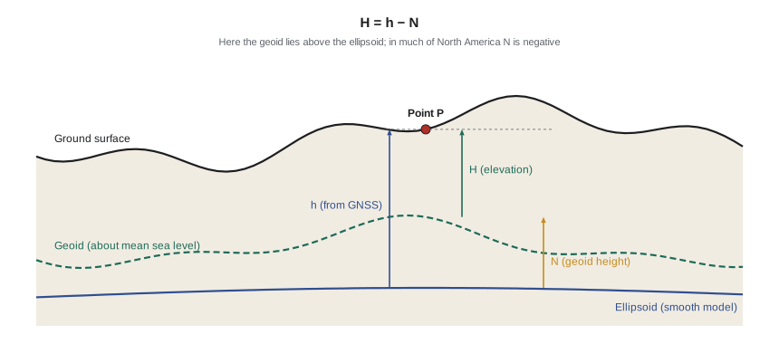
The US vertical datum is NAVD88, the North American Vertical Datum of 1988, tied to a network of leveled benchmarks. Older drawings may use NGVD29, which can differ from NAVD88 by more than a meter in parts of the West. NGS plans to replace NAVD88 with a geoid-based datum (NAPGD2022). Drawings should state which vertical datum they use, and the surveyor should confirm that the project benchmarks agree.
A benchmark is a stable, permanent point of known elevation. On a construction site, the surveyor will usually establish several temporary benchmarks (TBMs) close to the work, carried by leveling from a published benchmark or from GNSS. Many drawings also use a project datum, such as a finished floor of 100.000, which must be tied to the real vertical datum so that site grading and utilities connect correctly to the surrounding streets.
Units, precision and recording
US construction survey work is usually done in decimal feet, recorded to two decimal places (the nearest hundredth of a foot, about 1/8 inch). Carpenters work in feet, inches and fractions, so conversions are constant: 0.01 ft is about 1/8 inch and 0.08 ft is about 1 inch. Angles are measured in degrees, minutes and seconds. Stationing is written in hundreds of feet, so 12+50.00 means 1,250 feet from the start of the alignment. Federal highway and some public projects are designed in metric units.
| Conversion | Value |
|---|---|
| 1 inch | 0.0833 ft; 0.01 ft is about 1/8 in |
| 1 foot | 0.3048 m exactly (international foot) |
| 1 cubic yard | 27 cubic feet = 0.7646 m³ |
| 1 acre | 43,560 sq ft |
| 1 degree | 60 minutes; 1 minute = 60 seconds |
Field notes are legal and technical records. Whether written in a field book or stored in a data collector, they should record the date, crew, weather, instrument, control used, setup points, every measurement and any check. Never erase a field book entry; strike it through with a single line so it remains legible, and write the correct value beside it. Electronic files should be backed up daily and kept with the project records.
Errors, mistakes, accuracy and precision
No measurement is exact. Surveyors distinguish three kinds of departure from the true value.
- Mistakes, or blunders, are human errors such as reading 2.437 as 2.473, setting up on the wrong point, entering a backsight to the wrong control or recording a value in the wrong column. They can be any size and do not follow any pattern. They are caught by checks and redundant measurements, never by careful arithmetic.
- Systematic errors follow a physical law and have the same sign and size under the same conditions: a tape that is 5 mm too long, an instrument whose line of sight is not quite level, temperature expanding a steel tape, or the wrong prism constant. They accumulate, so they must be removed by calibration, correction or procedure, such as balancing backsight and foresight distances.
- Random errors are the small unavoidable variations left after mistakes and systematic errors are removed, such as tiny differences in pointing or reading. They are equally likely to be positive or negative, and they tend to partly cancel when many measurements are combined.
Accuracy is how close a measurement is to the true value. Precision is how closely repeated measurements agree with each other. A set of measurements can be precise but inaccurate if a systematic error shifts them all, for example a total station with the wrong prism constant entered gives consistent but wrong distances. Good surveying aims for both: precision through careful procedure, and accuracy through calibration and ties to known control.
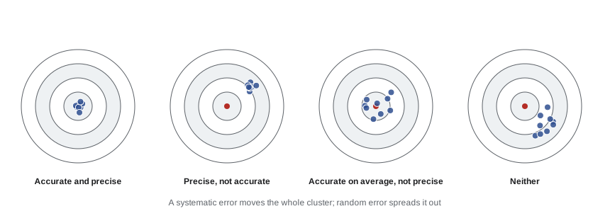
Random errors combine according to the square root of the number of measurements. If each of n independent measurements has a standard error e, the error of their sum grows as e × √n, while the error of their mean shrinks as e ÷ √n. This explains why a long level run accumulates error and why surveyors repeat important angles several times.
Worked problem
Error in a series of measurements
A distance is measured as 16 tape lengths. The random error of each tape length is ±0.01 ft. What is the expected random error of the whole distance?
Show solution
- Errors in a sum grow with the square root of the number of measurements.
- E = 0.01 × √16 = 0.01 × 4 = ±0.04 ft.
- Note that it is not 16 × 0.01 = 0.16 ft, because random errors partly cancel. A systematic error of 0.01 ft per tape length would add to 0.16 ft.
Answer: About ±0.04 ft of random error.
Checks, redundancy and closure
The single most important habit in surveying is checking. A measurement that has not been checked should be treated as a possible mistake. Surveyors build checks into every procedure.
- Close every level loop and traverse back on a known point, and compare the misclosure to the allowable value.
- Measure building diagonals: if the four sides and both diagonals of a rectangle agree, the corners are square.
- Tie layout points to at least two control points, and check one control point from another before staking.
- Have a second person or a second method check critical layout, such as anchor bolts or the first floor gridlines, before concrete is placed.
- Compare layout to known physical features: if the new curb line is 300 mm into the existing sidewalk, stop and investigate.
Closure is expressed as a ratio or a misclosure. For a traverse, the relative precision might be 1:10,000, meaning one unit of error per 10,000 units of distance traveled. For leveling, the allowable misclosure is usually a constant times the square root of the distance leveled, reflecting the way random errors grow. Specifications for control surveys set these values; you will calculate them in the next two lessons.
Tolerances: what accuracy does the work need?
Survey accuracy should match what the work requires. Rough grading may tolerate 30 to 50 millimeters; formwork for a concrete wall might need 6 to 10 millimeters; anchor bolts for steel columns typically need a few millimeters; and elevator rails or precision machinery bases need even less. The rule of thumb is that survey error should consume no more than a fraction of the construction tolerance, often a quarter to a half, so that the trades have room to work.
Tolerances come from the specifications and from referenced standards, such as ACI 117 for concrete construction tolerances and the AISC Code of Standard Practice for anchor rods and column placement.
When a tolerance is not stated, ask. A layout that is 'close enough' for the excavator may be useless for the precast fabricator.
Common mistakes
MistakeAssuming that every set of coordinates on a project is in the same system.
InsteadConfirm the datum, projection, units and whether coordinates are grid or ground before staking anything; get the transformation in writing.
MistakeUsing a GNSS rover without checking the geoid model and site calibration.
InsteadElevations depend on the geoid model and calibration; check the rover on a known benchmark at the start of every day.
MistakeMixing CGVD28 and CGVD2013, or NGVD29 and NAVD88, elevations.
InsteadOld and new vertical datums can differ by tens of centimeters or more; every drawing should state its datum.
MistakeTreating precise measurements as accurate.
InsteadConsistent readings can share a systematic error; calibrate instruments and tie to independent control.
MistakeSkipping checks to save time.
InsteadA blunder in layout can cost far more than a day of survey; close loops, measure diagonals and check from a second control point.
MistakeAsking a construction surveyor to locate a property line.
InsteadOnly a licensed land surveyor can establish legal boundaries.
Summary and key terms
- Licensed land surveyors establish legal boundaries; construction surveyors and field engineers lay out the work from control.
- Most construction layout is plane surveying, but grid coordinates, scale factors and geoid models link it to geodetic datums.
- NAD83 with State Plane coordinates and NAVD88 heights are the usual US reference systems, with a modernized system on the way.
- GNSS measures ellipsoidal height; elevations are orthometric heights found with H = h − N.
- Mistakes are caught by checks; systematic errors are removed by calibration and procedure; random errors are reduced by repetition.
- Random errors in a sum grow with the square root of the number of measurements.
- Survey accuracy should use only part of the construction tolerance.
- Plane surveying
- Surveying that treats the site as a flat surface, adequate for most construction layout.
- Datum
- A defined reference for coordinates or heights.
- Ellipsoid
- A smooth mathematical model of the earth used for horizontal positions and GNSS heights.
- Geoid
- A surface of equal gravity potential close to mean sea level; elevations are measured from it.
- Orthometric height
- Height above the geoid, the elevation used on drawings.
- Scale factor
- The ratio of a grid distance to the corresponding ground distance.
- Benchmark
- A stable point of known elevation.
- Blunder
- A mistake in measuring, reading or recording.
- Systematic error
- An error that follows a physical law and accumulates with the same sign.
- Precision
- How closely repeated measurements agree.
- Accuracy
- How close a measurement is to the true value.
Practice problems
Work each problem on paper first, then reveal the answer to check.
Who may establish a legal property boundary?
Show answer
Only a licensed land surveyor.
What is the difference between ellipsoidal height and orthometric height?
Show answer
Ellipsoidal height is measured from the ellipsoid by GNSS; orthometric height is measured from the geoid and is the elevation used on drawings.
A GNSS rover reads an ellipsoidal height of 237.58 ft where the geoid height is −118.50 ft. What is the elevation?
Show answer
H = h − N = 237.58 − (−118.50) = 356.08 ft.
A tape is known to be 4 mm too long. What kind of error is this?
Show answer
A systematic error; it accumulates and must be corrected.
A ground distance of 600.00 ft is measured where the combined scale factor is 0.99975. What is the grid distance?
Show answer
600.00 × 0.99975 = 599.85 ft.
Each of 9 setups contributes ±0.005 ft of random error. What is the total random error?
Show answer
0.005 × √9 = ±0.015 ft.
Give two ways to catch a blunder in building layout.
Show answer
Measure the diagonals, close back on control, check from a second control point or have a second person check.
Why should drawings state the vertical datum?
Show answer
Different vertical datums can differ by tens of centimeters or more, so grades and connections to existing utilities could be wrong.
Lesson quiz · 5 questions
Score 60% or more to complete this lesson.
Create a free account to save your progress, take quizzes and earn a certificate.