
CON-250 · Lesson 6 of 12 · 30 min
Building layout and control
Layout is where design becomes physical. A building's position on its lot, the spacing of its gridlines, the height of its floors and the location of every anchor bolt, sleeve and embed are all set by layout. Most of it is done by surveyors and field engineers, but the construction manager is responsible for making sure it is planned, protected, checked and recorded. This lesson follows building layout from the first review of the drawings, through the control network, the building corners and gridlines, foundations and anchor bolts, to transferring control up a multi-story structure and recording what was built.
Planning the layout
Good layout starts before anyone goes on site. The layout plan answers a few questions: which control will be used, who sets which points, what tolerances apply, how points will be protected and how layout will be checked. On a building project the work typically divides into the land surveyor's work (boundary, building location, primary control and certificates), the layout surveyor's work (gridlines, offsets, elevations) and the trades' layout from those marks.
The first task is a drawing review. The field engineer or surveyor should check that:
- The site plan ties the building to the property lines or to coordinates, and the setbacks agree with zoning and the permit.
- Gridline dimensions on the architectural, structural and mechanical drawings agree, and add up to the overall dimensions.
- Coordinates in the digital model, if provided, agree with the drawing dimensions when inversed.
- Elevations are on a stated datum, and the floor elevations, top of footing and site grades are consistent.
- Curved or skewed elements are defined clearly enough to stake, with radius points or coordinates.
Discrepancies go to the design team as requests for information before layout begins. A dimension string that does not add up is far cheaper to resolve on paper than after footings are poured.
The control network
Primary control is a set of stable, precisely located points around the site, established by the surveyor and tied to the project coordinate system and vertical datum. On a building site there are usually at least four primary control points, placed far enough from the excavation and from equipment routes that they will survive the whole project, with sight lines to the building area. Secondary control is denser, set closer to the work for convenience, and checked from the primary points.
Control monuments might be steel bars driven into the ground and encased in concrete, survey nails in curbs or sidewalks, brass discs in existing structures, or adhesive targets on neighboring buildings for resection. Benchmarks for elevation should be on things that do not move with frost or traffic: existing building foundations, bridge abutments or deep-driven rods.
| Control element | Typical form | Purpose | Protection |
|---|---|---|---|
| Primary horizontal control | Concrete-encased bar or disc, outside the work zone | Basis for all layout | Fence or barrier, paint, sign, regular checks |
| Benchmarks | Disc on an existing foundation or deep rod | Elevation reference | Away from frost, traffic and excavation |
| Resection targets | Adhesive prism targets on adjacent structures | Free-station setups anywhere on site | Located high and out of reach, recorded with photographs |
| Offset hubs and gridline marks | Hubs and tacks, paint, nails in slabs | Working layout for trades | Re-established as work proceeds |
Every control point is listed on a control sheet with its coordinates, elevation, description and a sketch or photograph. The control sheet is issued to every party doing layout, and updated whenever a point is lost or replaced.
Locating the building and setting gridlines
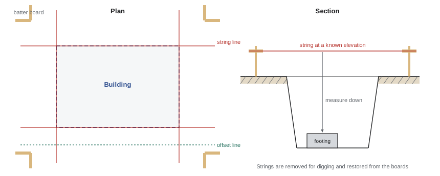
With control in place, the surveyor stakes the building's key points: usually the intersections of the main gridlines, or the building corners. Excavation will destroy anything placed at the actual building line, so most of the working layout is done on offsets: lines parallel to the gridlines, typically 1 to 3 meters outside the work, marked with hubs or nails. From offset hubs, a crew can restore a gridline at any time by measuring the offset distance back in.
On small buildings, batter boards are still used. A batter board is a horizontal board nailed to stakes outside each corner, with nails or saw cuts marking the building line. String lines stretched between opposite batter boards cross at the building corners and can be removed for excavation and restored afterwards. The top of the batter board is often set at a known elevation, such as the top of the foundation wall, so that the string line also gives the grade.
Checking square: diagonals and the 3-4-5 rule
A rectangle with correct side lengths is not necessarily square: a parallelogram can have the same sides. Equal diagonals prove a rectangle. For small layouts, the 3-4-5 rule (or any multiple, such as 6-8-10 or 9-12-15) sets a right angle with only a tape: if one side is 3 units and the adjacent side 4 units, the diagonal between their ends is 5 units exactly when the angle is 90°.
When diagonals differ, the difference indicates how far out of square the layout is. For a rectangle of sides a (the side being skewed) and b with design diagonal d, a skew of s at the far side changes one diagonal by about s × a ÷ d and the other by the same amount the other way, so the far corners should be moved by about half the difference times d ÷ a.
Worked problem
Diagonal check
A building 120.00 ft by 80.00 ft is laid out. The design diagonal is 144.22 ft. The measured diagonals are 144.30 ft and 144.14 ft. Is the layout square, and roughly how far is it skewed?
Show solution
- Design diagonal: √(120² + 80²) = 144.22 ft.
- Difference between diagonals: 144.30 − 144.14 = 0.16 ft.
- Skew s ≈ 0.16 × 144.22 ÷ (2 × 120) = 0.096 ft.
- The far side is about 0.10 ft (1-1/8 inch) out of square. Re-check the corners from control and re-set them before forming.
Answer: No: about 0.10 ft of skew; correct before forming.
Excavation and foundations
Excavation layout gives the operator the limits, the depth and the slope or shoring line. Typical stakes mark the top of the cut and carry an offset and a cut figure, such as '2.0 m offset, cut 3.15 to bottom of footing'. Machine control, covered in Lesson 12, increasingly replaces stakes for bulk excavation, but footings and pile caps still need precise layout.
For footings, the surveyor or field engineer sets the footing corners or centerlines and the top of footing elevation, usually on rebar stakes or grade pins in the excavation. Before concrete is placed, the forms are checked against the gridlines and elevations. For walls, a chalk line on the footing marks the wall face, and the top of wall elevation is marked on the forms.
Anchor bolts for steel columns are the most demanding foundation layout task. They are set using a plywood or steel template that holds the bolt group in the right pattern, located on the gridlines and set to the correct projection. Bolts that are out of position cause costly delays when the steel arrives.
The AISC Code of Standard Practice sets tolerances for anchor rods: rods within a group must be within 1/8 inch of each other center to center, and the center of each group must be within 1/4 inch of the established column line. Base plate elevations are set with leveling nuts, shims or grout pads. Always check the project specification.
A good practice is an independent check of all anchor bolt groups after the concrete is placed and before the steel arrives, recorded on a survey plot showing each group's offset from the gridlines. The steel erector receives the survey before starting, so any problems can be resolved in advance rather than with a crane waiting.
Elevation control
Each footing, slab and floor needs its elevation set and checked. On a single level, a rotating laser or level from a benchmark sets formwork heights, screed rails and pins. Benchmarks should be carried into the building early, and transferred to each floor as it is built.
To transfer elevations up a building, a steel tape is hung down a column, a stair or a shaft from the upper floor, and read with a level on both floors. The difference between the readings, plus or minus the level readings, gives the elevation of a mark on the upper floor. Total stations can also carry elevations up by trigonometric heights to targets on the upper floor, checked by a second method.
Worked problem
Carrying an elevation up a column
A level on Level 1 reads 4.68 on the benchmark (elevation 329.02 ft) and 1.68 on a steel tape hanging down a column. On Level 2, a level reads 15.98 on the tape, and 4.53 on a mark on the column. What is the elevation of the mark?
Show solution
- Level 1 HI = 329.02 + 4.68 = 333.70 ft. This line of sight cuts the tape at the 1.68 ft reading.
- The tape reading at the Level 2 line of sight is 15.98 ft, which is 15.98 − 1.68 = 14.30 ft higher.
- Level 2 HI = 333.70 + 14.30 = 348.00 ft.
- Mark = 348.00 − 4.53 = 343.47 ft. Apply the tape temperature correction for long transfers.
Answer: The mark is at 343.47 ft.
Transferring control up a building
As a building rises, gridlines must be re-established on each floor without accumulating error. The two common methods are vertical transfer and resection.
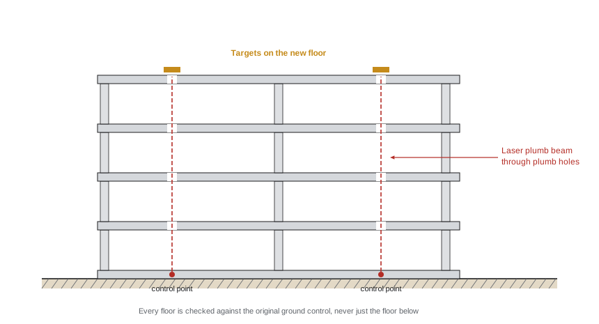
- Vertical transfer: small sleeves, or plumb holes, are left in each slab directly above control points set on the ground floor slab. A laser plumb or optical plumb, centered over the lower point, projects it up through the holes to a target on the new floor. Four or more points are transferred, forming a figure whose sides and diagonals are measured to check them. Gridlines are then laid out from these points.
- Resection: a robotic total station on the new floor measures to resection targets on surrounding buildings or to control on the ground, computing its position. This avoids plumb holes but depends on good targets and geometry, and on correct elevation data.
Whichever method is used, control on each floor should always be transferred from the original ground-level control, not from the floor below, so that errors do not build up story by story. The transferred points are checked against each other: if the design distance between two transferred points is 30.000 meters and they measure 30.006 meters, the difference is acceptable for most buildings; if they measure 30.030 meters, something is wrong.
Columns, walls and cores also need to be checked for plumbness as they are built. A common steel tolerance is 1 in 500 between splice points, with limits on cumulative deviation over the building height. Concrete walls and cores have similar limits in the concrete tolerance standards. A field engineer who checks plumbness on every lift prevents small deviations from becoming a building that is several centimeters out at the top.
Worked problem
Plumbness tolerance
A steel column is 14.00 ft tall between splices. The tolerance is 1:500. What is the maximum allowable out-of-plumb at the top? The surveyor measures 0.25 inch. Does it pass?
Show solution
- Allowable = 14.00 × 12 ÷ 500 = 0.336 inch, about 11/32 inch.
- Measured 0.25 inch is less, so it passes.
- Record it; also check cumulative deviation from the building's original control lines.
Answer: Allowable about 0.34 inch; 0.25 inch passes.
Interior layout, embeds and openings
Inside the building, gridlines and offset lines are snapped onto each slab, and the trades lay out walls, doors, equipment pads and fixtures from them. Embeds, sleeves and openings in slabs and walls must be placed before concrete, and their positions coordinated across trades. Robotic total stations driven directly from the building model now lay out hundreds of sleeve and hanger locations per day, and the as-built positions are recorded and compared with the model.
The construction manager's role here is coordination: making sure the model or drawings used for layout are the current, coordinated version, that each trade knows which control lines to use, and that someone checks critical items, such as elevator openings, stair openings and large mechanical penetrations, before concrete is placed.
Tolerances, the layout log and as-builts
Layout should be recorded in a layout log or field book: what was set, from which control, by whom, on what date, and what checks were made. A simple layout request system, where a trade asks for points and the layout team records what was given, prevents disputes about who set what.
When the work is complete, as-built surveys record where things actually are. These include foundation location certificates required by many municipalities, anchor bolt surveys, slab elevation and flatness surveys, utility as-builts and final site grading surveys. They protect the owner, the designer and the contractor, and they become the starting point for future work on the building.
| Item | Typical tolerance (illustrative) | Where to find it |
|---|---|---|
| Building location on lot | Within the setback limits; often 0.1 to 0.15 ft | Survey and zoning approvals |
| Gridlines on a floor | ±1/8 to 1/4 in between adjacent lines | Specification, ACI 117, AISC Code of Standard Practice |
| Anchor rods within a group | 1/8 in center to center | AISC Code of Standard Practice |
| Footing elevation | ±1/2 in up, −2 in down (ACI 117 for footings) | ACI 117, specification |
| Steel column plumbness | 1:500 between splices | AISC Code of Standard Practice |
Common mistakes
MistakeStarting layout before reviewing the drawings.
InsteadCheck dimensions, coordinates and elevations across disciplines first, and send discrepancies as RFIs.
MistakePlacing control points where equipment will destroy them.
InsteadSet primary control well outside the work zone and protect it with barriers and paint.
MistakeAccepting a layout because the side lengths are right.
InsteadMeasure both diagonals; equal sides do not prove square corners.
MistakeTransferring gridlines from the floor below.
InsteadTransfer from the original ground control on every floor to avoid cumulative errors.
MistakeLeaving the anchor bolt check until the steel arrives.
InsteadSurvey every bolt group after concrete placement and send the results to the erector in advance.
MistakeNot recording who set which points.
InsteadKeep a layout log and a request system so every point can be traced to its control and its author.
Summary and key terms
- Layout begins with a drawing review that checks dimensions, coordinates and elevations across disciplines.
- Primary control sits outside the work, is protected and is listed on a control sheet issued to every crew.
- Offset lines and batter boards preserve building lines through excavation.
- Equal diagonals prove a rectangle; the 3-4-5 rule sets right angles with a tape.
- Anchor bolts have tight tolerances; survey them before the steel arrives.
- Elevations are carried up with tapes and levels or by trigonometric heights, with checks.
- Control on every floor is transferred from the original ground control, and plumbness is checked on every lift.
- A layout log and as-built surveys record what was set and what was built.
- Primary control
- Stable, precisely located points that are the basis of all layout on a project.
- Control sheet
- A list of control points with coordinates, elevations and descriptions.
- Offset line
- A line parallel to a building or gridline, used to restore it after excavation.
- Batter board
- A horizontal board on stakes that holds string lines marking building lines.
- 3-4-5 rule
- A method of setting a right angle using the sides of a 3-4-5 triangle.
- Anchor bolt template
- A frame that holds a group of anchor bolts in position during concrete placement.
- Plumb hole
- A small sleeve in a slab used to transfer control vertically.
- Laser plumb
- An instrument that projects a vertical laser beam for transferring points.
- As-built survey
- A survey recording the actual position of completed work.
- Layout log
- A record of what layout was set, from which control, when and by whom.
Practice problems
Work each problem on paper first, then reveal the answer to check.
What is the diagonal of a 45.00 ft by 60.00 ft rectangle?
Show answer
75.00 ft.
A right angle is needed with a tape. Give a multiple of 3-4-5 that would work for a large footing.
Show answer
6-8-10, 9-12-15 or 12-16-20 (any multiple).
Why are offset hubs used instead of stakes on the building line?
Show answer
Excavation destroys stakes on the building line; offsets survive and allow the line to be restored.
A 12.00 ft tall column has a plumbness tolerance of 1:500. What is the allowable deviation?
Show answer
0.29 inch.
Why transfer control from the ground floor on every floor?
Show answer
So errors do not accumulate floor by floor.
What should happen to anchor bolt groups after concrete placement?
Show answer
They should be surveyed, with offsets from gridlines recorded and sent to the steel erector before erection.
Give three items to check in a pre-layout drawing review.
Show answer
Gridline dimensions across disciplines, overall dimensions, coordinates against dimensions, setbacks, datum and elevations, curve definitions.
What is a layout log for?
Show answer
To record what was set, from which control, when and by whom, and the checks made.
Lesson quiz · 5 questions
Score 60% or more to complete this lesson.
Create a free account to save your progress, take quizzes and earn a certificate.