
CON-110 · Lesson 6 of 12 · 25 min
Deep foundations: piles, caissons and ground improvement
When the soil near the surface is too weak or compressible to support a building, or when loads are very large, foundations must reach deeper, stronger layers or develop resistance along their length. Deep foundations, mainly piles and drilled shafts, carry loads down through weak soils to competent soil or rock. They are common for high-rise buildings, bridges, industrial plants, buildings on soft clays and fills, waterfront structures and sites with high groundwater. Deep foundation work is usually carried out by specialist subcontractors with heavy equipment, and it is often on the critical path of the schedule. This lesson explains how deep foundations carry load, the main types, installation methods, testing and quality control, common problems and the ground improvement alternatives that can sometimes replace them.
How deep foundations carry load
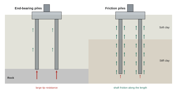
A pile or shaft carries load in two ways: end bearing, the resistance of the soil or rock at its tip, and shaft (skin) friction, the resistance along its sides. End-bearing piles transfer load mainly to a hard layer such as rock or dense gravel; friction piles develop most of their resistance along their length in soils without a strong bearing layer. Most piles combine both. Piles also resist uplift (tension), for example under buildings with large wind or seismic overturning forces or where groundwater pushes up on basements, and lateral loads from wind, earthquakes, soil pressure or ships at docks.
Here \(q_t\) is the unit tip resistance, \(A_t\) the tip area, \(f_s\) the unit shaft resistance in each soil layer and \(A_s\) the shaft surface area in that layer. Designers apply factors of safety or resistance factors, and confirm capacity by testing.
Driven piles
Driven piles are prefabricated elements forced into the ground by impact hammers or vibratory drivers. Common types include:
- Steel H-piles: rolled steel sections that penetrate dense soils and can be driven to rock; easy to splice and cut.
- Steel pipe piles: open- or closed-ended pipes, sometimes filled with concrete after driving.
- Precast prestressed concrete piles: square or octagonal concrete piles, durable and economical for large projects, but heavier and harder to splice or cut.
- Timber piles: used for light loads and marine structures in some regions.
Driven piles displace or densify soil and their driving resistance gives an indication of capacity: as a pile penetrates harder material, the number of blows per unit of penetration increases. Driving criteria, set by the engineer, specify the required set (penetration per blow or blows per 25 mm or per inch) and minimum tip elevation. Driving is noisy and causes vibration, which can disturb neighbours and damage nearby structures, so it is often restricted in urban areas. Piles can be damaged by hard driving, deviate from vertical, or refuse on boulders before reaching the required depth.
Drilled and cast-in-place foundations
Drilled foundations are formed by excavating a hole and filling it with reinforcing steel and concrete:
- Drilled shafts, also called caissons or bored piles, are large-diameter holes, from about 0.6 m to 3 m (2 to 10 ft) or more, drilled with rotary rigs. They can carry very large loads and are common for high-rise buildings and bridges. Where the soil caves or groundwater enters, the hole is supported by temporary steel casing or by drilling fluid (bentonite or polymer slurry), and concrete is placed from the bottom up with a tremie pipe, displacing the fluid.
- Belled caissons have an enlarged base to increase end bearing in stiff clays.
- Continuous flight auger (CFA) piles, also called auger cast piles, are drilled with a hollow-stem auger; concrete or grout is pumped through the stem as the auger is withdrawn, then reinforcement is pushed into the fresh concrete. They are fast, quiet and produce little vibration, but require careful monitoring because the hole is never open for inspection.
- Drilled displacement piles push soil sideways rather than removing it, reducing spoil.
- Micropiles: small-diameter, high-capacity drilled and grouted piles, useful in restricted access, for underpinning and in rocky or obstructed ground.
- Helical piles (screw piles): steel shafts with helical plates screwed into the ground by hydraulic motors; quick to install, immediately loadable and popular for light buildings, additions, decks and towers.
| Type | Typical use | Key advantages | Key cautions |
|---|---|---|---|
| Driven steel H-pile | Heavy loads to rock or dense soil | Robust, easy to splice | Noise and vibration |
| Precast concrete pile | Large projects, marine work | Durable, economical | Heavy, hard to cut or splice |
| Drilled shaft (caisson) | High-rise buildings, bridges | Very high capacity, inspectable | Groundwater and caving need casing or slurry |
| CFA (auger cast) pile | Urban sites, medium loads | Quiet, low vibration, fast | Hole never open; needs monitoring |
| Micropile | Underpinning, limited access | Small rigs, high capacity | Higher cost per unit load |
| Helical pile | Light buildings, additions | Fast, loadable immediately | Limited capacity, corrosion protection |
Pile caps, grade beams and connections
Piles are usually installed in groups and connected by reinforced concrete pile caps, which distribute column loads to the piles. Grade beams span between pile caps to support walls and tie the foundation together. After installation, piles are cut off to the specified elevation, the top of concrete piles may be broken down to expose reinforcement, and reinforcement is lapped into the cap. Pile positions are surveyed after installation, because piles often deviate slightly from their intended positions; if deviations exceed tolerances, the engineer may redesign the cap or require additional piles.
Testing and quality control
Because the pile itself cannot be seen once installed, quality control relies on records and tests:
- Installation records: for driven piles, the hammer type, blows per unit penetration, final set and tip elevation; for drilled shafts, depth, soil and rock encountered, casing, cleaning of the base, concrete volumes compared with theoretical volumes, and inspection of the base.
- Static load tests: loading a test pile with jacks against a reaction frame or kentledge and measuring settlement; the most reliable test, but slow and expensive.
- Dynamic testing: attaching sensors to a pile and analysing the stress waves from a hammer blow (pile driving analyser, PDA) to estimate capacity and check driving stresses.
- Rapid load tests and bidirectional tests, in which a jack cast into the shaft pushes up and down simultaneously.
- Integrity testing: low-strain sonic tests, crosshole sonic logging and thermal integrity profiling to detect defects such as necking, voids or soil inclusions in cast-in-place piles.
Specifications define the number of piles to be tested, the acceptance criteria and the inspection required. Inspection of deep foundations is usually performed by the geotechnical engineer or a special inspector.
In Canada, deep foundation design and inspection follow the National Building Code (Part 4), provincial codes and the Canadian Foundation Engineering Manual, with CSA standards for materials; the engineer of record specifies testing and field review.
Worked problem
Checking concrete volume in a drilled shaft
A drilled shaft is 900 mm in diameter (about 3 ft) and 14 m deep (about 46 ft). The concrete truck tickets show 10.2 m³ delivered and placed in the shaft. What is the theoretical volume, and what might the difference indicate?
Show solution
- Area: π × 0.45² ≈ 0.636 m².
- Theoretical volume: 0.636 × 14 ≈ 8.9 m³ (about 11.6 yd³).
- Overpour: 10.2 − 8.9 = 1.3 m³, about 15 % more than theoretical.
- Some overpour is normal because holes are slightly oversized and irregular; a large overpour may indicate caving or a cavity, while an underpour could indicate necking or soil intrusion, so the inspector compares actual and theoretical volumes for every shaft and investigates anomalies.
Answer: Theoretical volume is about 8.9 m³; the 15 % overpour is plausible but should be recorded and compared with other shafts.
Common problems
Deep foundation work faces characteristic problems: obstructions such as boulders, old foundations and debris that stop piles or deflect drills; piles that do not reach the required set or tip elevation; heave of previously driven piles as nearby piles displace soil; caving and groundwater in drilled holes; contamination of concrete with soil or slurry; damage from vibration to neighbours; buried utilities; spoil disposal, especially if contaminated; and access for large rigs on small or soft sites, which may need working platforms of compacted granular material designed to support the rig safely. Close cooperation between the general contractor, the specialist subcontractor and the geotechnical engineer is essential.
Ground improvement
Sometimes, instead of reaching through weak soils, the soil itself can be improved so that shallow foundations or slabs can be used. Ground improvement methods include preloading and surcharging soft clays with temporary fill, often with prefabricated vertical drains to speed consolidation; dynamic compaction, dropping heavy weights to densify loose fills and sands; vibro-compaction and stone columns, using vibrating probes to densify sands or form columns of compacted stone in weaker soils; rigid inclusions, columns of grout or concrete beneath a load transfer platform; deep soil mixing, blending cement into soil to form columns or blocks; jet grouting; and compaction or permeation grouting. These methods can be cheaper and faster than piles, but their design and verification require specialist engineers.
Choosing a deep foundation system
The choice of deep foundation is a balance between ground conditions, loads, site constraints, schedule and cost. On a site with soft clay over rock at 15 m, driven steel H-piles seated on rock might be the most economical choice in an open suburban area, while drilled shafts socketed into the rock might be chosen for very heavy column loads, and CFA piles or drilled displacement piles might be preferred in a dense urban neighbourhood where vibration and noise are not acceptable. Where headroom is limited, for example inside an existing building, micropiles installed with small rigs may be the only practical option. For a small addition or a deck, helical piles installed in a day by a compact machine are often the cheapest and fastest.
The geotechnical engineer usually recommends one or more suitable systems in the report, and the structural engineer designs the foundation layout. In some contracts, the pile type is specified; in others, a specialist contractor proposes a design-build solution that meets performance criteria. Either way, constructors must understand the installation requirements because they drive the schedule: driven piles can be installed quickly but may need time for set-up before testing, drilled shafts require concrete delivery coordinated with drilling, and all systems need access for rigs, cranes and concrete trucks.
Schedule and logistics
Deep foundation work is often on the critical path because nothing else can start until piles and caps are in place. A typical sequence is to prepare a working platform, set out pile positions, install test piles and carry out load testing, confirm the design lengths and criteria, install production piles, survey as-built positions, excavate and trim pile tops, place pile cap and grade beam reinforcement and formwork, and pour caps. Delays at any stage, such as a failed test pile, obstructions or late delivery of steel piles, push back the entire project. Experienced project managers schedule test piles early, order long-lead materials in advance, and plan for contingencies such as extra pile lengths or splices.
Spoil management is another logistical issue. Drilled shafts and CFA piles produce large volumes of excavated soil mixed with water or slurry, which must be stored, dried and hauled away, sometimes as contaminated soil with special disposal requirements. Slurry must be stored, recycled and disposed of properly. Driven piles produce little spoil but need storage areas for long steel sections or precast concrete piles, and safe handling with cranes.
Monitoring neighbours
Because pile driving and drilling can cause vibration, ground movement and noise, many projects include a monitoring program. Vibration monitors placed on neighbouring buildings record peak particle velocities and compare them with limits set in the specifications, which are lower for older or sensitive buildings. Survey points detect settlement or heave. Pre-construction condition surveys document existing cracks so that new damage can be identified fairly. Communication with neighbours, such as notices before noisy work begins, can prevent many complaints.
Common mistakes
MistakeAssuming a pile reached capacity without records.
InsteadRecord installation data and follow testing requirements.
MistakeIgnoring vibration from pile driving near neighbours.
InsteadMonitor vibration and consider quieter methods.
MistakePlacing concrete in a wet hole without tremie or slurry procedures.
InsteadUse casing, slurry and tremie methods as specified.
MistakeBuilding pile caps without checking as-built pile positions.
InsteadSurvey piles and have deviations reviewed.
MistakeNeglecting working platforms for piling rigs.
InsteadProvide designed platforms to keep rigs stable.
Summary and key terms
- Deep foundations carry loads through weak soils by end bearing and shaft friction.
- Driven piles include steel H, pipe, precast concrete and timber piles.
- Drilled shafts, CFA piles, micropiles and helical piles are installed without driving.
- Pile caps and grade beams connect piles to the structure.
- Records, load tests, dynamic tests and integrity tests verify capacity and quality.
- Obstructions, groundwater, vibration and access are common challenges.
- Ground improvement can sometimes replace deep foundations.
- End bearing
- Resistance at the tip of a pile.
- Shaft friction
- Resistance along the sides of a pile.
- Driven pile
- Prefabricated pile hammered or vibrated into the ground.
- Set
- Penetration of a pile per hammer blow.
- Drilled shaft
- Large drilled hole filled with reinforced concrete; a caisson.
- Tremie
- Pipe placing concrete from the bottom of a hole.
- CFA pile
- Continuous flight auger pile grouted through the auger.
- Helical pile
- Steel shaft with helical plates screwed into the ground.
- Pile cap
- Concrete block connecting a group of piles.
- Integrity testing
- Tests detecting defects in installed piles.
Practice problems
Work each problem on paper first, then reveal the answer to check.
What two mechanisms carry pile loads?
Show answer
End bearing and shaft friction.
When are friction piles used?
Show answer
Where there is no strong bearing layer at reasonable depth.
Name two driven pile types.
Show answer
Steel H, steel pipe, precast concrete, timber.
Why are CFA piles popular in cities?
Show answer
Quiet, low vibration, fast.
What is a tremie used for?
Show answer
Placing concrete from the bottom up in wet holes.
Theoretical volume of a 0.6 m diameter, 10 m shaft?
Show answer
About 2.83 m³.
What does a PDA test measure?
Show answer
Stress waves to estimate capacity and driving stresses.
Why survey piles after installation?
Show answer
To check deviations before building caps.
Name two ground improvement methods.
Show answer
Preloading, dynamic compaction, stone columns, soil mixing, rigid inclusions.
Why do piling rigs need working platforms?
Show answer
To keep heavy rigs stable on weak ground.
Lesson quiz · 5 questions
Score 60% or more to complete this lesson.
Create a free account to save your progress, take quizzes and earn a certificate.